Publication No. HRMCR11 Rev. B.0
About This Manual 27
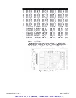
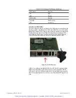
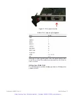
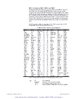
Front Panel Interfaces
CR11 Connectors
i
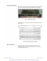
Refer to the next drawng for the location of interfaces on the front panel of the
CR! I and CTI I single slot board
(
either with front I/0 or with dual PMC):
Figure 7: Single slot f
r
ont panel
This drawing indicates the location of interfaces on the front panel of the CPI I
dual slot board:
f:00�
OOOOi'.,
f�OO�
OOOOi�
Figure 8: Dual and single slot f
r
ont panels
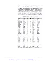
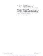
This chapter describes coru1ector pin assignruents on the CR! I. A pin
assigmnent description for available transition module can be found in the
corresponding appendix chapters
.
Artisan Technology Group - Quality Instrumentation ... Guaranteed | (888) 88-SOURCE | www.artisantg.com


