


Solares
TM
Smart Spa Parts Manual
CD0039
22
Rev:1121
Replacement Instructions
Warning! Work should only be done in electrical boxes by a qualified technician! Failure to connect
wiring properly could lead to electrocution, Product Malfunction, or a Fire!
Part #1 - 3AG 1A Fast Acting Fuse; 250V
1.
Disconnect tub from power by unplugging the tub or turning off the power switch on the
electrical box.
Warning! Failure to do so could result in electrocution!
2.
Disconnect remedy box from tub per instructions in “Part #1 –
Remedy Box Assembly” above.
You can leave UV lamps connected and just rotate the box 180° to bring it far enough out from
the tub to service it.
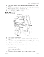
3.
Remove Remedy box cover by loosening the 4 screws located in each corner and lifting it off the
box.
4.
Flip up the top of the fuse holder marked “H” above
and open the left side.
5.
Remove blown fuse and replace with new fuse.
6.
Close side and lower top of holder back into base. Top should sit securely in base.
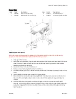
Part # 2
–
UV Ballast; High-Output
1.
Disconnect tub from power by unplugging the tub or turning off the power switch on the
electrical box.
Warning! Failure to do so could result in electrocution!
2.
Disconnect remedy box from tub per instructions in “Part #1 –
Remedy Box Assembly” above.
You can leave UV lamps connected and just rotate the box 180° to bring it far enough out from
the tub to service it.
3.
Remove Remedy box cover by loosening the 4 screws located in each corner and lifting it off the
box.
4.
Disconnect all ballast wires from the terminal blocks by applying pressure to orange button
adjacent to each connection using small screwdriver and pulling on wire. *To remove wires from
fuse holders you’ll need to place a small flathead screwdriver all the way into the adjacent hole
and then push it towards the main body of the fuse holder to release the wire.
5.
Remove the screws on either end of the ballast and pull ballast from box.
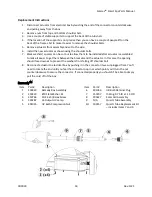
6.
Install new ballast with what, black and green wires on the same side of the box as the green
terminal block.
7.
Connect all wires per wiring list next to bottom image above. The item on the left of the arrow is
the wire color and the item on the right is the location to install that wire. (Adjacent image is
labeled with these locations.
8.
Once you are sure the ballast is wired correctly you can replace the cover and reinstall the
remedy box on the tub.
9.
Connect box to main power box using M12 connector labeled “Remedy”
10.
Power tub back on and verify correct operation in the outputs section of the maintenance
screen. (See operation manual.)