background image

Solares

TM

 Smart Spa Parts Manual 


CD0039 

Rev:1121 


For Assistance Contact:


Apollo Corporation 

450 Main St 

Somerset, WI 54025 

+1 (715) 247-5625 

Fax +1 (715) 247-3424 

[email protected]


https://apollobath.com


The information in this manual is subject to change without notice. 

In no event will Apollo Corporation be liable for technical or editorial omissions made herein; nor for direct, 

special, incidental, or consequential damages resulting from the furnishing, performance, or use of this 

material. 

This manual is copyrighted with all rights reserved. Under the copyright laws, this manual may not be copied, in 

whole or part, without the written consent of Apollo Corporation.


Содержание Solares Smart Spa

Страница 1: ...450 Main Street Somerset WI 54025 Phone 715 247 5625 Fax 715 247 3424 Website http www apollobath com SolaresTM Smart Spa Parts Manual ...

Страница 2: ...ual is subject to change without notice In no event will Apollo Corporation be liable for technical or editorial omissions made herein nor for direct special incidental or consequential damages resulting from the furnishing performance or use of this material This manual is copyrighted with all rights reserved Under the copyright laws this manual may not be copied in whole or part without the writ...

Страница 3: ... Valve 13 Docking Components 16 RemedyTM 18 Remedy Ballast and Fuse 21 Power Hub 23 Power Hub Fuses and Relays 24 Power Hub Power Supply and Stepper Driver 26 HMI 28 Tilt Switch 29 Door 30 Door Components 31 Secure Glide Transfer System 33 Chair Assembly Front 34 Chair Assembly Back 35 Carrier Base Assembly 37 Preventative Maintenance Schedule 39 Errors 41 ...

Страница 4: ...e nut and washer from underside of pump 3 Remove old pump and install new one 4 Replace washer and nut on underside of tub 5 Slide hose over tube and replace clamp Part 3 4 Skin Care Hose Assembly Shampoo Oil 1 Unscrew end of hose from jug of product and set on cardboard 2 Pump out as much as shampoo oil as possible to clear access from line 3 Use screwdriver to disengage cable clamp from hose 4 R...

Страница 5: ...Soc Cap Screw 3 8 16 x 3 0 6 330302 Momentary Switch Push Button 2 350703 Soc Cap Screw 3 8 16 x 2 5 7 401041 LH Tub Transfer Beam 3 320549 TRX Jet Dir Internal BN 8 340538 Gasket 3 8 ID x 1 OD x 1 4 4 401040 RH Tub Transfer Beam 9 350512 3 8 Star Washer SS 5 320572 94GPM Suction Cover BN 10 350077 3 8 16 Thread Hex Nut ...

Страница 6: ... the section of the cover without any holes is facing up as to ensure optimal drainage 4 Replace screw in center of part Part 6 Momentary Switch Push Button 1 Remove right side panel and right side panel trim 2 Switch off tub power using power switch on electrical box or unplug tub from wall Warning Failure to do so could result in electric shock 3 Use small chancel locks or pliers to remove nut o...

Страница 7: ...ttings and gaskets from valve 4 Disconnect cable from old assembly on tub 5 Remove screws and remove valve from plumbing 6 Discard old gaskets and valve 7 Apply new gaskets to PVC fittings on either side of old assembly large ID side of gasket fits over ridge of fitting 8 Place the new valve between the two halves of the old assembly and push parts together as shown above Valve handle should face ...

Страница 8: ...from the pump 4 Disconnect the unions from the top and side of the pump 5 Loosen the hose clamp securing the check valve to the top port of the pump and slide it off 6 Remove the three bolts mounting the pump in place and set the pump aside 7 Install the new pump on the frame using the hardware as shown above Note The long bolt secures the highest foot of the pump 8 Reattach the unions to the side...

Страница 9: ...0728 PH Mach screw 8 32 x 2 1 4 10 200442 Spa Care Hose Assembly Cleaner 5 350696 8 Start Washer 11 200443 SPA Care Hose Assembly Disinfectant 6 330300 NTC Thermistor 10Kohm Replacement Instructions Part 1 Fresh Water Manifold Assembly 1 Turn off hot cold water supply 2 Use touch screen to briefly open shower or fill valve to blead the water pressure from the system 3 Disconnect all DIN cables fro...

Страница 10: ...t to injector pull hose off barb Note If you have Vinyl tubing available it is often easier to carefully cut along the length of the tubing to remove it from the barbs and simply replace it as it can be stubborn 3 Twist injector counterclockwise to remove from street elbow 4 Remove barb metering tip from old injector and install on new injector 5 Install new injector into street elbow 6 Replace ho...

Страница 11: ...ce rubber seal from new valve in the impression on the manifold with the large stainless plate facing up Carefully push edges of gasket into the impression It s very important that the gasket lines up with the impression exactly 8 Place the spring on top of the nub coming out of the center of the stainless plate 9 Place the valve on top making sure that the side of the valve with the bump on its f...

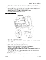
Страница 12: ...mb screw located towards back side of cutout 3 Remove screws securing lower part of frame Detail B and let front of frame rotate downward 4 Remove screws shown in detail A while supporting frame 5 Pull frame down and out to remove from tub 6 When ready to reinstall start by tucking front of trim into front edge of tub 7 Slide trim up until top edge of trim is recessed behind tub shell 8 Align rear...

Страница 13: ... 17 Stepper Motor 3 350762 Carriage Bolt 8 32 X 3 4 7 350508 Machine Screw 6 32 x 3 8 SS 4 350438 8 32 Coarse Thread Nylock Nut 8 350725 PH Mach Screw M3 0 5 x 8mm Replacement Instructions Part 1 Mixing Valve Assembly 1 Remove side panels and side panel trim 2 Turn off hot cold water supply 3 Use touch screen to briefly open tub or shower valve to bleed pressure form lines 4 Remove fill hoses from...

Страница 14: ...en wrench 3 Loosen 4mm screw on other side of pully using 2 5mm allen wrench 4 Lift large pulley off of valve You may need to loosen the screws on the top of the adjacent plate to create some play 5 Remove screw fastening down brass adjustment knob 6 Remove both white clips from Rada assembly 7 Remove black cap and brass adjustment knob 8 Twist off top piece of brass assembly 9 Pull Rada out of br...

Страница 15: ...screws down on its back side to secure it into that position 27 Turn the large pulley counterclockwise just past the point in which the inductive sensor s light part 5 turns on 28 Use 2mm hex wrench to tighten set screw good in snug to lock pulley in position 29 Verify that pulley rotates clockwise without a problem and trips the sensor when rotating back counterclockwise without having to force i...

Страница 16: ... to verify that screw coming off pulley does not hit inductive sensor and that sensor turns on when screw get in front of it Adjust sensor as needed by loosening the top sensor bracket screw to achieve this if it s out of position 2 5mm allen key 10 Connect M12 cable to stepper motor Docking Components Item Part Description Item Part Description 1 330277 24VDC Sealed Rotary Latch 5 350477 Star Was...

Страница 17: ...roximity Sensor 8mm x 40mm 1 Disconnect M8 cable from back of sensor 2 Remove lock nut from front of sensor 3 Thread sensor out of the back of the frame 4 Thread new sensor into frame so that tip is 0 56 from the front of the frame 5 Thread lock nut onto front of sensor to secure it in position 6 Reconnect M8 cable 7 Verify correct installation of sensor by docking carrier Sensor light should be o...

Страница 18: ...ator is assembled to make it easier to get them between the brackets and the actuator In this case the opening should face down as to prevent the washers from falling off shoulder bolt 8 Reconnect actuator to electrical box by pushing it in the connector it was unplugged from You ll need to rotate the end until you feel the connector pop in at which point you ll turn the nut counterclockwise to se...

Страница 19: ...or to verify chamber holds water Warning Do not stand inline with the quartz tube while pump is running If assembly is reassembled incorrectly the tube could eject from the chamber Part 4 High Output UV Bulb 1 If replacing the top UV bulb then you will need to remove the side panel trim on the left side of the tub to get access 2 Tilt tub to its lowest position 3 Disconnect tub from power by unplu...

Страница 20: ... of the chamber Tilting bulb too early could result in quartz tube breakage 6 Remove part 5 7 Place your finger in the quartz tube Part 9 and pull the tube out of the chamber 8 Install part 7 on the open end of the new quartz tube and carefully slide it into the chamber Use a thin dull implement like a tongue suppressor to push the gasket in tight around the tube 9 Replace part 5 ensuring it is ti...

Страница 21: ...rts Manual CD0039 21 Rev 1121 15 Remedy Ballast and Fuse Item Part Description Item Part Description 1 330341 3AG 1A Fast Acting Fuse 250V 3 350756 10 24 X 3 8 Screw 2 330283 UV Ballast High Output 4 350229 10 Flat Washer SS ...

Страница 22: ...y box from tub per instructions in Part 1 Remedy Box Assembly above You can leave UV lamps connected and just rotate the box 180 to bring it far enough out from the tub to service it 3 Remove Remedy box cover by loosening the 4 screws located in each corner and lifting it off the box 4 Disconnect all ballast wires from the terminal blocks by applying pressure to orange button adjacent to each conn...

Страница 23: ... two screws located towards the bottom of the sensor 3 Loosen all screws on cover and remove it 4 Remove screws fastening electrical box to tub frame 5 Pull electrical box out of tub Cables can be removed from cable clips by pulling on lever on the front 6 Install new electrical box using hardware as shown above 7 Make all electrical connections per drawing 08 0312 Install water level sensors in b...

Страница 24: ...NT Hosp Plug 6 330385 Rep Cube SPST Relay 6A 24V 2 330343 3AG 6A Fast Acting Fuse 250V 7 330387 Rep Cube DPDT Relay 12A 24V 3 330341 3AG 1A Fast Acting Fuse 250V 8 330388 Rep Cube SPST Relay 9A 24V 4 330232 3AG 4A Time Delay Fuse 250V 9 330386 Rep Cube DPDT Relay 8A 24V 5 330396 Rep Cube SPST Relay 16A 24V 10 330342 3AG 5A Time Delay Fuse 250V ...

Страница 25: ...g Failure to do so could result in electrocution 3 Loosen screws holding on electrical box cover until they are free of the box and remove the cover 4 Disconnect old cable from terminal blocks by pushing orange button down with small flathead screwdriver and pulling out cable 5 Loosen the strain relief and pull the cable out of the box 6 Trim outer jacket of new cable back to 1 5 7 Pass new cable ...

Страница 26: ... operation Part 5 6 7 8 and 9 1 Raise tub to highest position if it is not already in the up position 2 Unplug power cable from wall outlet Warning Failure to do so could result in electrocution 3 Loosen screws holding on electrical box cover until they are free of the box and remove the cover 4 Find the Relay to be serviced and pull back on the relay release lever to eject the relay 5 Line the pi...

Страница 27: ... as even with bottom of the power supply as possible 8 Mount the new power supply in the power hub using the previously removed screws 9 Wire power supply as follows a Green wire to Ground Connection b Brown wire to ACL c Blue wire to CAN d Both red wires to Vo e All black wires to COM 10 Replace the electrical box cover 11 Plug tub back in and verify correct operation Part 6 Stepper Motor Driver ...

Страница 28: ...enclosure USB cable will be in the way of HMI 7 Loosen screws on I O modules until screw is free of threads tilt them back and then lift out of HMI Leave wires connected to them and let them hang out the bottom of the enclosure 8 unplug the power plug ethernet cable USB cable and Serial connector from the HMI 9 Loosen HMI clamp screws until they are loose enough to tilt up and pull out of the slot...

Страница 29: ... s easiest to just reinstall the original modules of they are working correctly as this eliminates the need to migrate connector and reduced the risk of mixing up connections a If replacing the modules as well then you ll need to transfer the black connectors over to the new modules Note It is critical that they connectors get installed into the same slots Failure to install connectors in the same...

Страница 30: ...e 6 Move strain relief to new switch and insert wires 7 Connect wires on each side of normally open set of contacts 8 Replace cover and bolt switch back onto frame so that it s level with the tub frame 9 Power tub back on 10 Lower the tub an inch or so and then raise tub until it stops 11 Verify that tub rails are approximately level If rails are off then the height of the switch needs to be adjus...

Страница 31: ...6 Solares Outer Door Skin 2 500105 Door Latch Hardware 1 set 9 350550 Paddle Handle Actuator 3 350553 10 24 X Pan Head Screw SS 10 400711 Door Handle Plug 4 350300 10 Star Washer SS 11 400769 Door Plug Retainer 5 300175 Hexagonal Rod 12 350229 10 Flat Washer SS 6 350574 10 24 Spring Clip U Nut 13 350570 8 32 x 3 8 PH Head Screw 7 350576 10 24 x PH Screw ...

Страница 32: ...ugh the hole in the bottom of the skin and then through all pawls and the handle Which should be closed 8 Open the handle and tighten down the set screws to secure the rod 9 Replace screws around the perimeter of the door skin Part 1 Remote Compression Latch 1 Remove outer skin per above instructions 2 Replace latch 3 Verify that flat of latch is facing front of door If it is not then you ll have ...

Страница 33: ...SolaresTM Smart Spa Parts Manual CD0039 33 Rev 1121 3 Secure Glide Transfer System Item Part Description Item Part Description 1 220096 Chair Assembly 2 220093 Carrier Base Assembly ...

Страница 34: ...Part Description Item Part Description 1 401075 Lumbar Pad 5 350764 Hi PRO Soc HD Scw 20 X3 8 2 350449 7 Tub Handle Pull SS 6 420245 Seatbelt Buckle End 3 350738 Low Soc HD Cap Scw 20 x 3 4 7 350161 Flat Washer SS 4 350335 PH Mach Screw 20 X 1 8 350078 20 Coarse Thread Nylock Nut ...

Страница 35: ...vet Washer 1 8 Alum 9 401043 Stepper Wheel 1 5 8 Dia 4 350738 Low Soc HD Cap Screw x 3 4 10 350105 Flanged lock nut 5 16 18 5 350739 Bowden Cable 19 11 350504 Dome Blind Rivet 1 8 x 0 4 6 350761 HX Cap Screw 10 32 x 1 2 Replacement Instructions Part 1 Chair Push Handle Weldment 1 Push in on sides of part 2 to pop it out of part 1 2 Remove hardware from below part 1 and replace with new handle 3 Pu...

Страница 36: ...ackets 5 Rivet tongue fitting of Bowden cable onto release handle using Part 11 6 Use zip ties or other method to secure secondary release handle to fully raised position 7 Manually raise the secondary release lever as high as it will go and insert the wire from the Bowden cable underneath the head of the screw Note Cable should be installed towards the outside of the chair side closest to you to ...

Страница 37: ...oarse Thread Nylock Nut 7 350018 3 8 Flat Washer 24 350711 3 Diameter Wheel 8 350765 Hex Soc HD SCRW 28 x 5 8 25 350714 Shoulder Bolt x 2 9 420257 Armrest RH SS Insert 26 350518 3 8 16 Crse THD Nylock Jam Nut 10 420256 Armrest LH SS Insert 27 420260 Rotary Latch Modified 11 350743 Compression Sprint Closed End 28 350696 8 Star Washer 12 350081 3 8 16 Coarse Thread Nylk Nut 29 350608 20 Hex Bolt x ...

Страница 38: ...ecure itself firmly in the upright and locked position but shouldn t be difficult to pull to the side and release Part 3 0 94 ID Foam Grip 21 1 Cut off the old foam grip using utility knife 2 Rub some soap onto the armrest and slide the new foam grip over it by inching it along from the back end Part 13 Heavy Duty Swing Away Footrests 1 Pull out lever on the side of footrests Next to where they mo...

Страница 39: ...ely rounded Can hold carrier securely Thermostatic mixing valve X Verify unit adjusts temperature correctly when target temperature is changed Thermistor X Verify water temperature dispensed by tub fill matches temperature shown on the screen Remedy Bulbs X X Remove and clean annually if using Apollo cleaning solutions otherwise every six months Verify UV indicator lights and UV bulbs are working ...

Страница 40: ... X Verify release levers raise all the way up when release handle is lifted to the bar Cable X Ensure cable is secured under bolt in secondary lock levers and that it cannot pull out Verify rivets securing top of cable to handle are in good condition Release Levers X Verify that springs effectively drop release levers down after releasing handle Caster Locks X Casters lock tightly and prevent chai...

Страница 41: ...he thermometer is connected properly Unlikely resistance value was measured from the manifold thermometer Likely caused by the thermometer being disconnected or wired incorrectly Auto Reset Disables Valves 4 Temp Over Limit Temperature over the limit Verify Rada cartridge adjusted appropriately Rada unable to bring the water temperature down into an acceptable range Could be caused by the cold wat...

Страница 42: ...nsor indicate that UV lights didn t turn off when they should have Could also be caused by relay getting stuck in closed position This is the case if UV lights are truly on or by there being too much ambient light behind the tub Auto Reset 10 No Cold Supply Cold Supply Error Can t bring down water temp Check cold supply and verify pully secured to Rada shaft System unable to drop water temperature...

Отзывы: