background image


‐    ‐ 

24

6.6 Parts drawing-A6 


40-2

40-3

40-4

40-5

40-6

40-7

40-8

40-9

40-10

40-6

40-11

40-12

40-13

40-14

40-15

40-17

40-1

40

40-16

71

40-4

44-1

44

44-2

Содержание AutoLift AL-243156

Страница 1: ...DIRECTED MAY CAUSE INJURY OR DEATH Specifications subject to change without notice Note While all due care and attention has been taken in the preparation of this document Advance AutoQuip shall not be liable for any inaccuracies or omissions which may occur therein MOTORCYCLE HOIST AutoLift AL 243156 Extra Heavy Duty Electric Operated Motorcycle Hoist 1000Kg Maximum Lifting Capacity Design Code A...

Страница 2: ...2 2Technical Data 2 3Hydraulic Scheme 2 4 Circuit Diagram 3 Preparing and installation 3 1Site Selection 3 2Surface Condition 3 3Installation Instruction 3 4Preparation for Starting up 4 Operation 4 1Caution and Warning Label 4 2Operation Instructions 5 Maintenance Instructions 6 Parts Drawing and Parts Code List 7 Trouble Shooting Guide ...

Страница 3: ...ons 1 2 Important Information 1 Carefully read this manual thoroughly before installing operating or maintaining this hoist 2 This hoist is designed for indoor use only and should not be installed in a pit or depression 3 The lifts have specific electrical requirements as described in the Installation Instructions section of this manual 4 This hoist has a minimum ceiling height requirement as desc...

Страница 4: ...he hoist until contact is made with the vehicle Make sure that the pads and the ramps have properly engaged the vehicle before raising the hoist to a working height 7 Keep everyone clear of the hoist when the hoist is moving the locking mechanism is disengaged or the vehicle is in danger of falling 8 Unauthorized personnel should never be in the shop area when the hoist is in use 9 Inspect the hoi...

Страница 5: ...e not limited to the following cylinder replacement platform and safety latch replacement motor replacement control board replacement oil replacement and refilling lubrication 19 Anyone who will be in the vicinity of the hoist when it is in use should familiarize themselves with following Caution Warning and Safety related decals supplied with this hoist and replace them if the are illegible or mi...

Страница 6: ... 6 ...

Страница 7: ...r lifting motorcycles ATVs and safely holding them in an elevated position It consists of a fixed structural scissor lift and a remote controller 2 2 Technical Data Capacity 1 000 kg Lifting Height Max 1 200 mm Height Min 180 mm Width Overall 800 mm Platform Length Max 2 250 mm Platform Width 800 mm Electric Supply Tolerance 10 1HZ Power Unit 240V 50Hz 10A 1 1KW Ambient Air Temperature 5 40 Ambien...

Страница 8: ... 8 Fig 1 2250mm 785mm 800 mm 380 mm 562mm 1270 mm ...

Страница 9: ...2 3 1 5 9 Hydraulic Oil tank One way va Relief valve c Scheme 2 lve 6 10 Mesh Mesh Restrictor va 9 Fig 2 3 G 7 S alve 11 C Gear pump Solenoid valv Cylinder 4 M ve 8 R 12 P Motor Restrictor va Pipe lve ...

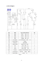
Страница 10: ...switch LA42MY 220V 10A 1 KM AC contactor NC1 09 10 24VAC 400V 9A 1 FR Overload relay TA25DU 1 TR transformer ABL6TS06B 1 BR bridge rectifier KBPC1010 1A 1000V 1 FU1 Fuse 5 20 delay 1A 2 FU2 Fuse 5 20 delay 3 15A 1 FU Fuses 6 30 delay 10A 2 MA1 AC motor ML802 4F 1PH 230V 50Hz 1 1KW 1 YV electromagnet TAU1564T 24VDC 520mA 2 YT Solenoid valve 24VDC 1A 1 ...

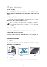
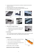
Страница 11: ...tion requirement may cause the hoist instability or personal injury Installing on asphalt soft clay floor or near the expansion gap is prohibited 3 3 Necessary Tools Rubber Hammer Sockets and Open End Wrenches Ratchet Driver Vice Grips 3 4 Personal Protective Equipment Always wear proper protective Equipment like working suit shoes gloves glasses etc 3 5 Installation Instruction 1 Unpacking Open t...

Страница 12: ...th 2 liters of hydraulic oil AW32 if empty b Change the tank plug black with a ventilating one brass Fig 12 4 Power Hooking Have a certificate electrician establish a 230V 50Hz 10A power supply to the motor through the plug A protection against indirect contact RCCB shall be provided by the user 3 6 Starting up 1 Raise the platform to full height by pressing the UP button 2 Lower the hoist to floo...

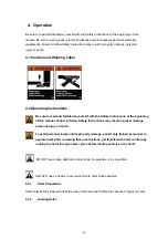
Страница 13: ... beginning of this manual Failure to follow Safety Instructions may result in proper damage personal injury or death To avoid personal injury and or property damage permit only trained personnel to operate hoist After reviewing these instructions get familiar with hoist controls by running the hoist through a few cycles before loading vehicle on the hoist DO NOT leave ramp attached to hoist while ...

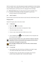
Страница 14: ... controller b Raise vehicle until the clear the floor then release the UP button c Check wheel clamps and secure straps d Continue to raise to desired height only if vehicle is secure on hoist e Push the PARKING button to lower the platform into the locking position and the locking latches will be engaged When any emergency situation comes press down the red emergency stop button immediately to st...

Страница 15: ... warning decals If hoist is not operating properly DO NOT use until adjustment or repairs are made by qualified hoist service personnel DO NOT using the PARKING button instead of the DOWN button NEVER press UP or DOWN button for a long time while the hoist is not moving or the whole control system will be damaged Relief the button if you find the hoist is not responding to the button actuated Once...

Страница 16: ...en off first loose the nuts on the wheel shaft and rest the wheel on the clamp b Loose the bolts on the platform end of the wheel board Then move them aside with hand hold the wheel clamp base c Lower the base together with the wheel slowly It will be easy to do service job of the wheel ...

Страница 17: ...er 9 Check safety latches for free movement and full engagement with hoist are working 9 Check hoses connections for leakage Every Month 9 Lubricate locking latch shafts Push latch handle several times for oil to penetrate joints 9 Lubricate the sliding pieces with heavy duty bearing grease 9 With hoist lowered check the hydraulic fluid level If necessary add oil as described in the Installation I...

Страница 18: ...y of the power unit is about 3L Refill with hydraulic oil if necessary AW 32 or 46 Non Detergent Non Foaming Anti Wear Hydraulic Oil 9 If hoist stops short of full rise or chatters contact your service provider 9 Replace all caution warning or safety related decals on the hoist If unable to read or missing Reorder labels from service provider 9 Check all components wear situation ...

Страница 19: ... 19 6 Parts Drawing and Parts Code List 6 1 Parts drawing A1 2 9 4 3 11 12 13 14 15 16 17 22 23 20 24 4 1 21 25 8 26 27 ...

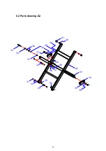
Страница 20: ... 20 6 2 Parts drawing A2 29 31 32 37 33 34 35 38 39 40 41 38 44 43 42 39 30 36 38 45 48 47 46 49 50 ...

Страница 21: ... 21 6 3 Parts drawing A3 29 31 52 53 54 55 31 66 51 51 65 59 60 57 56 58 61 62 63 64 54 4 68 67 27 72 72 27 ...

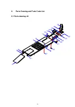
Страница 22: ... 22 6 4 Parts drawing A4 54 1 54 5 54 14 54 13 54 9 54 6 54 7 54 12 54 8 54 2 54 3 54 4 54 10 54 11 ...

Страница 23: ... 23 6 5 Parts drawing A5 1 6 5 10 28 ...

Страница 24: ... 24 6 6 Parts drawing A6 40 2 40 3 40 4 40 5 40 6 40 7 40 8 40 9 40 10 40 6 40 11 40 12 40 13 40 14 40 15 40 17 40 1 40 40 16 71 40 4 44 1 44 44 2 ...

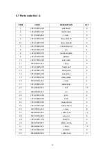
Страница 25: ...24 00025 000 hinge shaft 4 13 JP24 00021 000 sliding slot 2 14 JP24 08000 000 wheel slot 1 15 JP24 07000 000 sliding plate 1 16 5105 10014 000 screw 4 17 JP24 09000 000 wheel stop 1 20 5103 08025 000 bolt 16 21 5202 00008 000 nut 6 22 JP24 00018 000 βpin 2 23 JP24 00020 000 shaft 1 24 JP24 06000 000 hinged board 2 25 JP24 01007 000 rubber board 4 26 5107 05014 000 screw 8 27 5206 00005 000 selfloc...

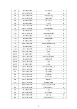
Страница 26: ... E clip 4 40 9 JP24 13003 000 arm shaft 3 40 10 JP24 00016 000 cover 2 40 11 5110 04020 000 screw 2 40 12 JP24 13001 000 long connecting bat 2 40 13 5206 00004 000 selflock nut 4 40 14 JP24 13200 000 arm 2 40 15 5110 04012 000 screw 6 40 16 JP24 13002 000 short connecting rod 2 40 17 JP24 13300 000 lock tongue 2 41 JP24 00004 000 upper roller 2 42 JP24 03000 000 out frame 1 43 JP24 02000 000 insid...

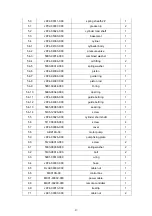
Страница 27: ...0 O ring 1 54 10 5906 00040 000 dust ring 1 54 11 JP24 04008 000 guide belt ring 1 54 12 JP24 04001 000 guide belt ring 1 54 13 5905 00060 000 seal ring 1 54 14 5105 12020 000 screw 1 55 JP24 00023 000 cylinder short shaft 1 56 5117 06008 000 screw 4 57 JP24 00006 000 cover 1 58 ABZ14S 00 motor pump 1 59 JP24 00026 000 pump fixing plate 1 60 5120 08010 000 screw 2 61 5303 00008 000 spring washer 2...

Страница 28: ... 28 72 5109 05020 000 threaded pin 2 ...

Страница 29: ... 29 6 8 Parts drawing B 2 9 10 12 13 14 16 19 20 22 23 24 25 5 15 11 8 7 1 3 6 18 17 4 6 21 ...

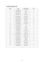
Страница 30: ...sher 4 10 JK01 10029 000 tapping screw 8 11 MK01 00105 000 rail 1 12 JK01 10010 100 fuse 1A 2 13 DK05 10008 000 fuse 10A 2 14 DK09 10007 000 fuse seat 1 15 JK01 10009 001 fuse seat board 1 16 JK01 10009 000 fuse seat 2 17 5110 04004 000 tapping screw 2 18 MK01 00102 000 bridge rectifier 1 19 JK01 10031 000 tapping screw 2 20 JK01 10005 000 contactor 1 21 JK01 10020 000 cable ring 2 22 JK01 10014 0...

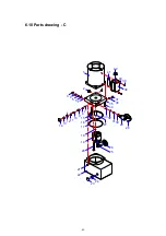
Страница 31: ... 31 6 10 Parts drawing C 1 7 2 6 5 4 3 7 8 9 10 11 12 13 14 15 16 17 18 19 20 21 22 24 23 25 26 33 32 31 30 29 27 34 35 36 37 38 40 39 41 28 42 ...

Страница 32: ...BZ01 04004 000 lock nut 1 14 BZ01 04 12 000 protect cap 1 15 BZ14 00001 000 return pipe 1 16 5901 01150 000 O ring 1 17 5901 01120 000 O ring 1 18 5901 00008 000 O ring 1 19 BZ02 03000 000 gear pump 1 20 5105 08075 000 bolt 2 21 5117 06008 000 selflock nut 4 22 BZ14 02100 000 tank 2 23 QY02 03002 000 vetilating cover 1 24 QY02 03002 000 combined seal washer 1 25 BZ14 01001 000 sucking pipe 1 26 BZ...

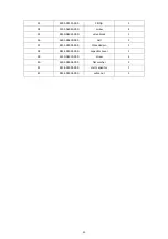
Страница 33: ...ew 4 35 BZ30 04001 000 valve block 1 36 5601 00800 000 ball 2 37 BZ01 00002 000 threaded pin 2 38 BZ14 05003 000 capacitor caver 1 39 5110 04010 000 screw 2 40 5302 00004 000 flat washer 2 41 BZ14 05002 000 start capacitor 1 42 BZ14 05004 000 cable nut 1 ...

Страница 34: ... in advance 4 Overloading hoist 1 Supply correct voltage to motor 2 Clean lowering valve 3 Reset the pressure of relief valve 4 Check vehicle weight and or balance vehicle weight on lift Hoist slowly settles down 1 Check valve is blocked 2 Lowering valve isn t opened fully 1 Clean check valve 2 Clean lowering valve Slow lifting speed 1 Air mixed with oil 2 Suction stub looses 3 Relief valve opens ...

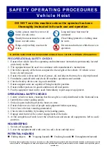
Страница 35: ...the capacity of the hoist compared to the weight of the vehicle If vehicle is too heavy do not proceed 4 Ensure the area is clean and clear of grease oil and objects that may be a slip trip hazard 5 Familiarise yourself with and check all machine operations and controls 6 Check all safety devices are in good condition 7 Ensure support arms are capable of being locked in position 8 Ensure rubber pa...

Страница 36: ...PECIFIC WARRANTY PROVISIONS FOR UNITS LOCATED OUTSIDE OF THESE COUNTRIES NOTE THE EQUIPMENT IS NOT TO BE USED FOR WASH DOWN PURPOSES OR TO BE INSTALLED IN AN OUTDOOR ENVIRONMENT WHERE IT IS SUBJECT TO WEATHER OR WATER DAMAGE WARRANTY WILL BE IMMEDIATELY VOID STRUCTURAL COMPONENTS ALL STRUCTURAL AND MECHANICAL COMPONENTS OF THIS UNIT ARE GUARANTEED FOR A PERIOD OF FIVE YEARS FROM THE DATE OF INVOIC...

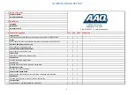
Страница 37: ...ety locks tested for correct operation Checked for good working order Supplied with the hoist and in good working order Checked for correct operation Hoist checked with load for correct operation and speed control tested Checked wire ropes for correct installation and tension Concrete floor is a suitable depth for installation Safety Devices Welds Hydraulic Equipment and Controls Pneumatic Equipme...

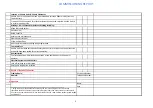
Страница 38: ...onstrated the operation of the vehicle hoist to the owner or operator Lock off isolating switch installed Emergency stop button installed 3 Details of Electrical Contractor Trading Name Address 4 Signature I being the person responsible for completing the commissioning report have exercised reasonable skill and competency when completing the report and herby certify that the vehicle hoist has been...

Отзывы: