


18
ECM Driven Fan
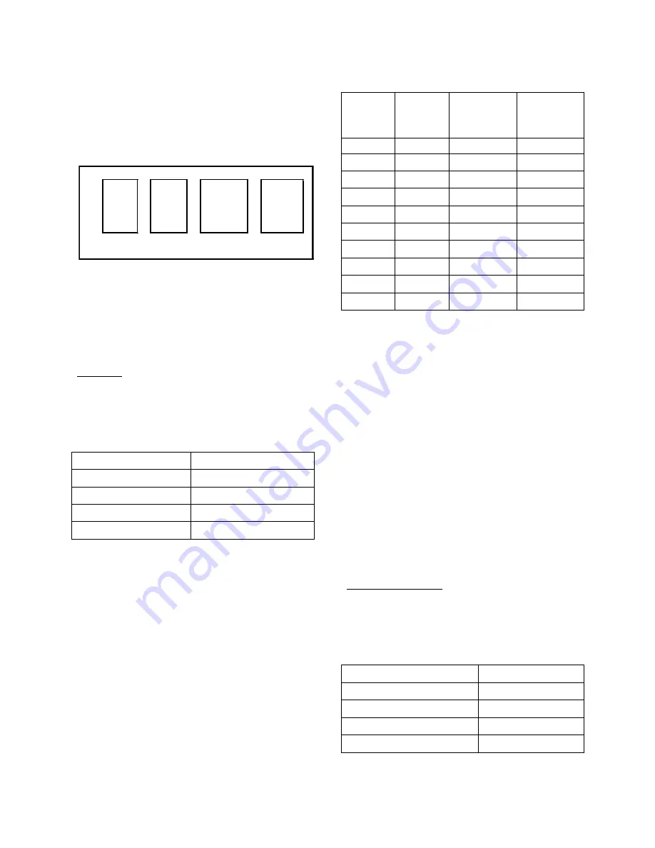
The Electrically Commutated Motor (ECM)
has selectable fan speeds as determined by
the configuration of four pins as shown in
FIGURE 2.
Figure 2 - Example Configuration of ECM
Fan Taps
Adjust the taps as desired for cooling,
dehumidification, and heating according to
the following instructions.
Cooling:
Units are preprogrammed from the factory
for a rated airflow rate of 400 cfm per ton as
shown in Table 3.
Table 3 - Factory Preset Air Flow
Model
Preset cfm
F1-060
2000
F1-048
1600
F1-036
1200
F1-024
800
* Maximum total static is 2.25” w.g.
The
high
speed for cooling may be selected
by setting the COOL and ADJUST fan
speed taps (shown in Figure 2). The setting
combinations are shown in Table 4.
Note: On the ADJUST tap, both of the ‘1’
selections have the same effect on motor
speed.
Table 4 - Cooling Fan Speed Tap Settings
F1-060/ F1-036/
COOL
Tap
ADJUST
Tap
F1-048
F1-024
(cfm)
(cfm)
2000
1200
A
1
2000
1200
D
1
1840
1150
B
+
1700
1020
A
-
1700
1020
D
-
1600
1000
B
1
1380
920
C
+
1360
850
B
-
1200
800
C
1
1020
680
C
-
A signal from the thermostat, showing a
need for dehumidification, will cause the
unit to slow the fan speed in order to allow
the air moving across the coil to get colder
thereby better dehumidifying the air. Fist
stage dehumidification has a low fan speed
of 67% of the selected max speed. Second
stage dehumidification has a fan speed of
45% of the selected max speed. NOTE: The
Modulating Hot Gas Reheat option must be
selected to have a second stage of
dehumidification.
In this comfort cooling application of the
ECM fan motor, heat and cool taps, A & D
have the same effect on motor speed.
Humidity Control:
Adjust the DELAY tap for humidity control
that is suitable for the climate according to
Table 5.
Table 5 - Climate Settings
CLIMATE
DELAY Tap
Humid
A
Sub-humid/Dry
B
Semi-Arid
C
Arid/Hyper-Arid
D
A
----
A
- -
1
- -
A
----
B
- -
B
- -
+
- -
B
- -
C
- -
C
- -
-
----
C
- -
D
- -
D
----
1
- -
D
- -
HEAT
COOL
ADJUST
DELAY
Содержание F1-060
Страница 31: ...31 ...
Страница 33: ...33 Figure 5 Modulating Hot Gas Reheat Piping Diagram with Air Handling Unit below Condensing Unit ...
Страница 36: ...36 Figure 8 Heat Pump Piping Diagram with Indoor Unit above Outdoor Unit ...
Страница 37: ...37 Figure 9 Heat Pump Piping Diagram with Outdoor Unit above Indoor Unit ...
Страница 38: ...38 Figure 10 Heat Pump Piping Diagram with Modulating Hot Gas Reheat and Indoor Unit above Outdoor Unit ...
Страница 39: ...39 Figure 11 Heat Pump Piping with Modulating Hot Gas Reheat and Outdoor Unit above Indoor Unit ...
Страница 40: ...40 Thermostat Installation and Wiring Figure 12 2 Stage Cooling with Electric Heat ...
Страница 41: ...41 Figure 13 2 Stage Cooling with Heat Pump and Electric Heat ...
Страница 42: ...42 Figure 14 2 Stage Cooling and Electric Heat with Hot Gas Reheat and Humidistat ...
Страница 43: ...43 Figure 15 Main Control Board for Units Equipped with Modulating Hot Gas Reheat ...
Страница 45: ...45 Figure 17 5kW Electric Heat ...
Страница 46: ...46 Figure 18 10 kW Electric Heat ...
Страница 47: ...47 Figure 19 15 kW Electric Heat ...
Страница 48: ...48 Figure 20 20 kW Electric Heat ...
Страница 49: ...49 Figure 21 25 kW Electric Heat ...
Страница 55: ...55 ...