9
C)
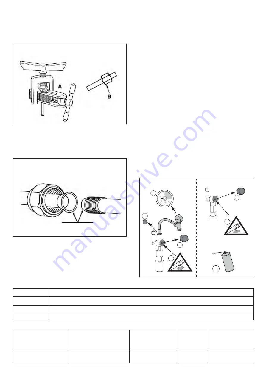
Flaring
(Fig. 3)
Remove the nuts fixed on the internal unit and
outside, put them on the pipe and carry out the
flaring and the removal of burrs, as previously
indicated
.
D)
Fastening of refrigeration pipes (Fig. 4)
Align the tubes by lubricating the outer surface of the
tubes pipes at the folder. Tighten
sufficiently the nut using two keys like
-
Precautions
PIPE CONNECTIONS
Fig. 3
PIPE CONNECTIONS
(
FIXING
)
Fig. 4
Tabella 4 -
Refrigerant charge
Model
s
Dislevel
H
Length piping
(m)
Max
(m) Max
Maximum length
addition of additional
refrigerant (g / m)
Quantity add.
refrigerant
(g/m)
3.0+3.0 - 7.8+3.0 - 7.8+7.8 - 7.8+7.8+3.0
7.8+7.8+7.8 - 7.8+7.8+7.8+7.8
5
15
5
20
Excessive torque can break the nut or crack the
folder. to avoid such dynamics use a suitable torque
wrench respectingthe tightening torque shown in
table 3
.
Tabella 3 -
Tightening torque
Diameter
Torque Diameter (N / m)
Ø 1/4
18
Ø 3/8
42
Ø 5/8
60
E)
Leak test of refrigeration lines
Fig. A
1
3
35 bar
4
2
WARNING
!
2
WARNING
!
5
1
Faucet on gas side
Faucet on liquid side
1) Open the caps of the sectioning valves
2) Check that the sectioning valves are
closed (Fig. A n ° 2).
3) Remove the cap from the service connection
on the sectioning valve (Fig. A No. 3).
4) Connect the pressure gauge and the
nitrogen bottle to the
stop valve then progressively
increase the pressure in the connection pipes
of the refrigerant and in the internal module at
35 bar, with
5 bar increments (Fig. A n ° 4).
5) Check the tightness of the fittings with a
spray
leak detector. If there are leaks,
repeat the operations in the order indicated e
check the seal again (Fig. A n ° 5).
6) Leave the circuit under nitrogen pressure for
at least 24 hours and check that at the end of
this time frame the initial pressure does not
goes down.
7) Release the pressure and the nitrogen.


