


Residen al Gas Tankless Water Heater Use and Care Guide • 33
INSTALLATION
Gas Conversion
Instruc ons
WARNING!
An improper
fi
eld
conversion could cause poten ally
dangerous condi ons that may
cause an explosion or
fi
re resul ng
in property damage, bodily injury or
both.
This water heater is con
fi
gured
for Natural Gas from the factory.
However, if a
fi
eld conversion to
Propane Gas is necessary, the
conversion kit and instruc ons
supplied with the water heater, and
must be used and installed by a
quali
fi
ed service agency.
Before you install the components in
this Propane Gas conversion kit, verify
the type of gas that will be used to
fuel the unit.
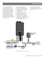
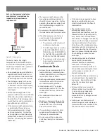
Water Connec ons
WARNING! Do not use this appliance
if any part has been under water.
Immediately contact a quali
fi
ed
installer or service agency to replace
a
fl
ooded water heater. Do not
a empt to repair the unit! It must be
replaced!
NOTICE: Do not reverse the hot
outlet and cold inlet connec ons to
the water heater. If you reverse the
connec ons, the water heater will not
ac vate properly.
Determine the type of water pipes in
your home. Use
fi
ngs appropriate
for the type of pipe in your home
(copper, CPVC, or PEX). Do not
use iron or PVC pipe – they are
not suitable for potable water. All
pipes, pipe
fi
ngs, valves and other
components, including soldering
materials, must be suitable for
potable water systems. Also, an
automa c air vent or air separator
must be installed when the water
heater operates in a closed loop
system such as a recircula on
system. Trapped air bubbles in the
water system can cause a pump to
cavitate or damage the water heater's
heat exchanger. This equipment
must be installed according to its
manufacturer's instruc ons.
• A manual shuto
ff
valve must be
installed on the cold water inlet to
the water heater between the main
water supply line and the water
heater.
• A thermal expansion tank or code
approved device to handle thermal
expansion must be installed.
• Connect the cold water supply using
3/4 inch Na onal Pipe Thread “NPT”
to the
fi
ng marked COLD.
• For ease of removing the water
heater for service or replacement,
connect the water pipes with a
union. We recommend using a di-
electric-type union (available at your
local plumbing supplier). Dielectric
unions can help prevent corrosion
caused by ny electric currents
common in copper water pipes and
can help extend the life of the water
heater.
• Connect the hot water supply using
3/4 inch NPT to the
fi
ng marked
HOT. Follow the same connec on
guidelines as for the cold water
supply.
• In addi on, a manual shuto
ff
valve is
also recommended on the hot water
outlet.
• Double check to make sure the hot
and cold water pipes are connected
to the correct hot and cold water
fi
ngs on the water heater.
• If needed, install (or adjust) the
home’s Pressure Reducing Valve.
• Before installing the water heater,
fl
ush the water line to remove all
debris, and a er installa on is com-
plete, purge the air from the line.
Failure to do so may cause damage
to the heater.
• There is a wire mesh
fi
lter within
the cold inlet to trap debris from en-
tering your heater. This will need to
be cleaned periodically to maintain
op mum
fl
ow.
• Install insula on (or heat tape) on
the water pipes especially if the
indoor installa on area is subject to
freezing temperatures. Insula ng
the hot water and return pipes will
reduce heat loss.
• If water hammer is evident install
water hammer arrestors on the inlet
side.
• A drain pan, or other means of
protec on against water damage, is
recommended to be installed under
the water heater in case of leaks.
IF YOU HAVE COPPER PIPES:
If your home has copper water
pipes, you can solder the water pipe
connec ons or use compression
fi
ngs which don’t require soldering.
Compression
fi
ngs are easier to
install than soldering pipe. Check with
local plumbing o
ffi
cials to determine
what types of pipe materials are
suitable for your loca on. Do not use
lead-based solder.
NOTICE: Do not solder pipes while
they are a ached to the water
heater. The water heater contains
non-metallic parts which could be
damaged. The proper way to connect
the water heater to copper water
pipes is as follows:
• Solder a short length of pipe (about
a foot or so) to a threaded adapter
using only 95/5 n an mony or
equivalent solder.
• A ach the threaded adapters to the
water heater’s connec ons (using
thread sealant tape or pipe joint
compound). Connect the home’s
water pipes by soldering, keeping
the connec ons at the water heater
cool with wet rags.
Содержание THR-160
Страница 44: ...Figure 40 Ligh ng Instruc ons 44 Residen al Gas Tankless Water Heater Use and Care Guide OPERATION...
Страница 64: ...64 Residen al Gas Water Heater Use and Care Guide COMPONENT LIST 1 18 22 3 20 4 6 21 28 14 25 13 2 7 12 34...
Страница 67: ...Residen al Gas Tankless Water Heater Use and Care Guide 67 COMPONENT LIST 29 17 32 31 30 33...
Страница 68: ...COMPONENT LIST 68 Residen al Gas Tankless Water Heater Use and Care Guide...
Страница 71: ...NOTES Residen al Gas Tankless Water Heater Use and Care Guide 71...
Страница 72: ...Copyright 2023 A O Smith All Rights Reserved...


