10
VIDEO WALL CONTROL SOFTWARE
The Video Wall Control software provides complete control over the Video Wall Rotation Processor via Ethernet or RS-232. This software
can scan the local network, as well as any RS-232 connections on the PC, for controllable units to add to the current video wall grouping.
Multiple video wall configurations can be stored in the software for quick local recall, or the configurations can be exported as a file for
use in other video wall deployments.
In addition to video wall design, creation, and positioning, this
software can also be used to configure the scaler mode of the
unit, if needed.
Software Operation
Please obtain the
“Video Wall Control”
software from our website for download and save it in a directory where you can easily find it.
Ensure that all the units you wish to control have been powered on and that they are all connected to the same network as your laptop/
PC. Start the software by double clicking on the
*.exe
file to start the Video Wall Control software.
By default, when the software starts, the layout will be empty. Dummy displays may be added to/removed from the layout using the
“+”/“−”
buttons in the
“Unit”
section if there are no live units available for control and the user wishes to visualize different display
arrangements. To add physical units to the layout, perform a
“Search”
.
Note:
This software is only compatible with Windows 7 or later PCs.
Video Wall Unit Search
By clicking on the
“Search”
button at the top-right corner of the window, all Video Wall Rotation Processors that are located on the local
network or are directly connected via RS-232 can automatically discovered. Each detected unit can then be added to the current video
wall layout and assigned a unique ID number.
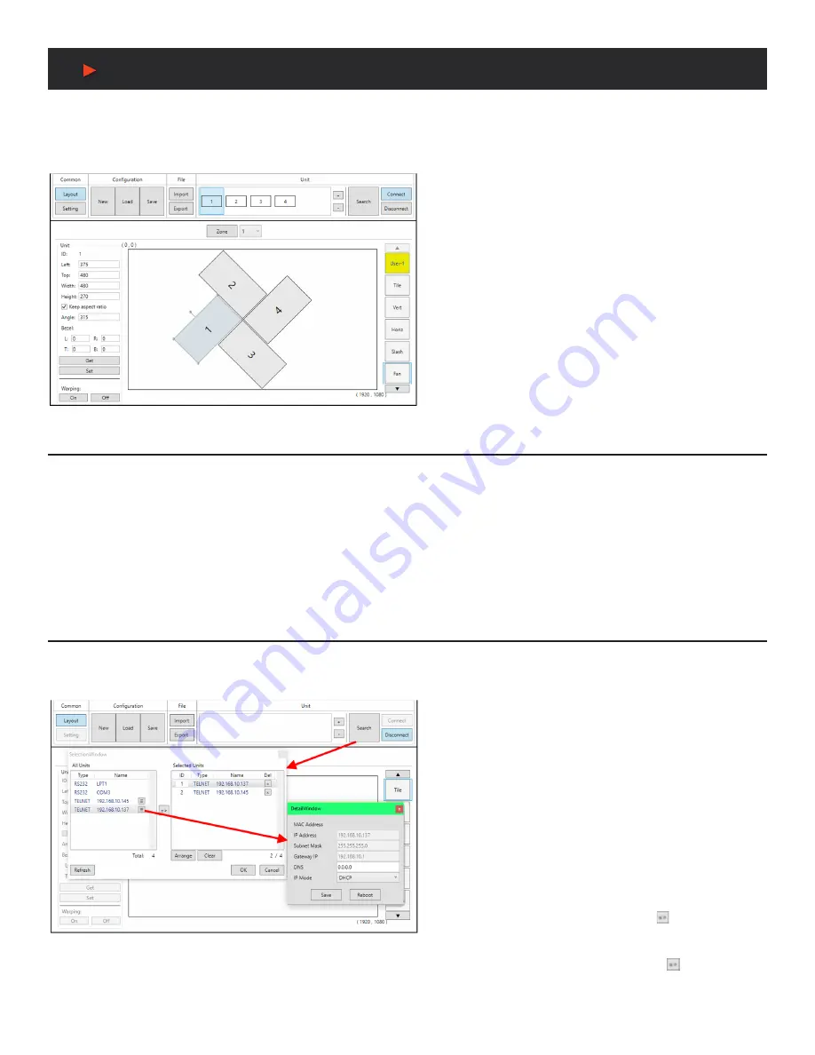
1. SEARCH BUTTON:
Click on the
“Search”
button to open the
Unit Selection Window. All detected units on the local network
as well as all available local serial ports will be listed in the
“All
Units”
section. After all units have been selected and arranged,
click on the
“OK”
button to add them to the layout.
Note:
Units connected via RS-232 can’t be directly detected,
so all available serial ports will be listed, even if they do not
currently have a connected unit.
■
ALL UNITS LIST:
All detected units on the local network
as well as all available local serial ports are listed here. All
detected units are identified by their IP address. If additional
units are added to the network after the window is opened,
click
“Refresh”
to detect them. Selecting a Unit (or serial port)
and then clicking the right arrow button ( ) will place them in
the Selected Units window in the order they are added. The
Ethernet details of each detected unit may also be changed
by clicking on the associated details icon ( ).
A
NEU
VIDEO
Содержание ANI-HDROTATE
Страница 21: ...19 CONNECTION DIAGRAM CONNECTION DIAGRAM BASIC SCREEN ARRAY SYSTEM A NEUVIDEO ...
Страница 22: ...20 CONNECTION DIAGRAM CONNECTION DIAGRAM ADVANCED SCREEN ARRAY SYSTEM A NEUVIDEO ...
Страница 23: ...21 CONNECTION DIAGRAM CONNECTION DIAGRAM 4K QUAD ZONE SCREEN ARRAY SYSTEM A NEUVIDEO ...


