3M
Multimedia Projector MP8620
Adjustments
3M 1999
1-7
3.4 Volts
0.1
Label
PCB
Trim
1-8.
Interface/Audio Board Synchronization
The interface board or the audio board must be in sync. If either one or both are changed, complete the
synchronization procedure.
1.
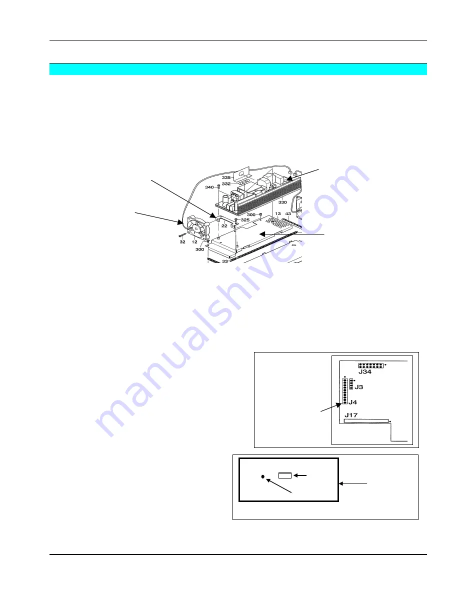
Remove the power supply board using the procedure listed in the Disassembly/Reassembly section.
2.
Remove the cooling fan and bracket by removing the two screws.
3.
Remove three additional screws on the power supply base plate.
4.
Tip up the base plate toward the lamp housing to remove it.
5.
Reconnect the power supply to the machine with the 3-pin connector, or reconnect the external power
supply (DY-0205-1509-3) to the machine with the 3-pin connector.
6.
Connect the interface board to the power board with the Service Interface Cable (DY-205-1500-1).
7.
Place a cover over the power supply board to prevent damage or injury.
Because the power supply board is fully energized in the next step, it is essential that a cover is placed over the
board to prevent injury.
8.
Power up the projector.
9.
Measure the voltage of pin 9 on the test block. This
connector is nearest the EPROM. Pin 1 is closest to
the EPROM. The voltage should be 3.4 Volts
.01.
10.
If the voltage reading of pin 9 on the test block is
outside the allowable tolerance, adjust the trim
potentiometer located in a small hole in the audio
board until the voltage reading is within tolerance.
11.
When finished with the adjustment, reassemble
the projector.
Use extra care when replacing the power supply
base plate, the LCD cable can be damaged very
easily.
Power supply
base plate
Power supply
board
Cooling fan bracket
Cooling fan


