EO Abator Operation and Installation Manual
12
Section 3: Installation Requirements
General Electrical Requirements
All internal wiring within the EO Abator system has been connected at the factory. External wiring must be in
accordance with local and/or national codes and plant procedures.
Connect a dedicated service to the main circuit breaker located inside the control box. A main disconnect is not
provided on the EO Abator System and needs to be included in the building installation. It must be mounted in close
proximity to the EO Abator system within easy reach of the operator, and shall be marked as the disconnecting device
for the EO Abator system.
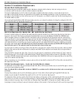
If connecting Model 50AN to 208 VAC single phase service, use a boost transformer to bring the voltage to 220 VAC
(recommended 7.5 to 10 KVA Boost transformer).
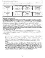
Model
Voltage
Current Rating
Main Breaker
Frequency
50AN
220-230VAC, 1 Phase
30A
40A
50/60Hz
50AE
400VAC, 3 Phase
17A
20A
50/60Hz
50AJ
200VAC, 3 Phase
28A
40A
50/60Hz
Electrical Requirements: Models 5XL, 8XL and GS Series Sterilizers
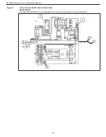
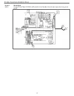
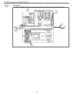
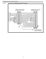
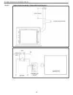
Connect corresponding wire numbers between indicator panel terminal strip and the control box terminal strip (see
Figures 2, 3, 5, and 6). Use three-pair (6 wire) shielded cables (recommended Belden 18 AWG Part #83656) and
limit the length of the wire to 40 M (130 ft.). The shield on the control panel end of the cable must be connected to
the ground lug in the control panel. A ground wire from the indicator panel to the EO Abator system is required. If the
indicator panel is within 12 M (40 ft.) from the EO Abator system, a 12 AWG ground wire should be used. If the length
is 12-24 M (41-80 ft.), a 10 AWG ground wire should be used. For 25-40 M (81-130 ft.) length, an 8 AWG ground wire
should be used.
In no case is the indicator panel to be mounted more than a maximum of 40 M (130 ft.) away from
the EO Abator system. The indicator panel must be located in the sterilizer area.
A ground wire from the ground lug in the control panel to earth ground is required. Use the same wire criteria as listed
above for the indicator panel to determine the proper wire AWG for the distance run between the control panel and
earth ground.
Using the DB-15 connector(s) with cable, connect wiring between the sterilizer(s) and the EO Abator system indicator
panel (see Figures 2, 3, 5, and 6). Install cable between the EO Abator system indicator panel and the Abator using 6
conductor 18 AWG shielded cable (recommended Belden Part #83656). A 3M service representative will connect the
wires to the Abator terminal strip.
When connecting only one sterilizer, a jumper wire must be connected from terminal 27 to 25 and from terminal 28 to
26 inside the control box.
EO Inlet Line Requirements – Vent Line from Sterilizer to Abator
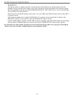
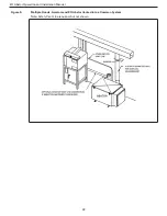
A combination of two Steri-Vac gas sterilizers Model 5XL, 8XL, or GS Series sterilizer may be vented through a common
vent line to the EO Abator system.
Note:
The Model 5XL or Model 8XL sterilizers CANNOT be combined with a GS Series sterilizer when connecting to
an Abator.
Connect the sterilizer vent line to the EO Abator system’s 1.9 cm (3/4 in.) National Pipe Thread (NPT) EO inlet. An
adapter may be needed to facilitate the need for a 2.5 cm (1.0 in.) vent line. See Figure 5.
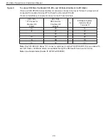
The diameter of the vent line used for the EO inlet and safety vent depends on the combined length of the two vent lines.
Use 2.5 cm (1 in.) to 3.8 cm (1.5 inch) copper tubing to connect sterilizer discharge to the EO Abator system EO inlet.
Refer to table for line sizes. Use a 1.9 cm (3/4 in.) National Pipe Thread (NPT) connection at the EO Abator system.
Avoid sags or loops in all lines to prevent moisture buildup at other points in the line. Ensure that the vent line is gas tight
Содержание 50AN
Страница 1: ...3 Operation and Installation Manual Models 50AN 50AE 50AJ EO Abator ...
Страница 20: ...EO Abator Operation and Installation Manual 19 Figure 3 For 5XL 8XL and GS Series Sterilizers D Connector ...
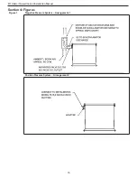
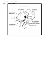
Страница 22: ...EO Abator Operation and Installation Manual 21 Figure 5 Clearances Required ...


