


7
WIRING AND FINISHING UP
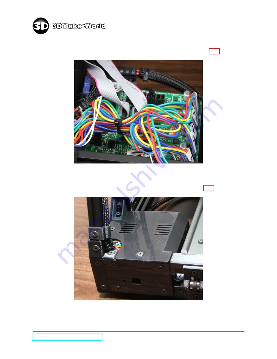
•
Secure extra length of motor cables using a zip tie as shown in Figure 7.25.
Figure 7.25: Closed electronics top cover after wire connection
•
Cover the electronics cabling with the top cover as shown in Figure 7.26.
Figure 7.26: Closing the electronics top cover (rear view)
109
Содержание Artifex 2
Страница 7: ...1 INTRODUCTION Figure 1 6 The technical specifications of Artifex 2 http 3dmakerworld com 8 ...
Страница 16: ...2 PACKING LIST 100 101 102 104 105 106 107 108 109 110 111 112 http 3dmakerworld com 17 ...
Страница 17: ...2 PACKING LIST 113 114 115 116 118 119 200 202 203 204 205 207 http 3dmakerworld com 18 ...
Страница 18: ...2 PACKING LIST 208 209 209R 210 211 215 216 227 220 221 222 223 http 3dmakerworld com 19 ...
Страница 19: ...2 PACKING LIST 224 225 226 300 300D 301 301L 301R 302 304 304D 305 http 3dmakerworld com 20 ...
Страница 20: ...2 PACKING LIST 400 404 405 406 500 501 502 Figure 2 4 List of printed parts http 3dmakerworld com 21 ...
Страница 117: ...8 ARTIFEX 2 DUO Figure 8 4 The assembled Artifex 2 Duo 3D printer http 3dmakerworld com 118 ...


