background image

3

LOWER FRAME AND COMPONENTS

3.2.3

Installing electronics board

Install electronics onto the bottom mount plate

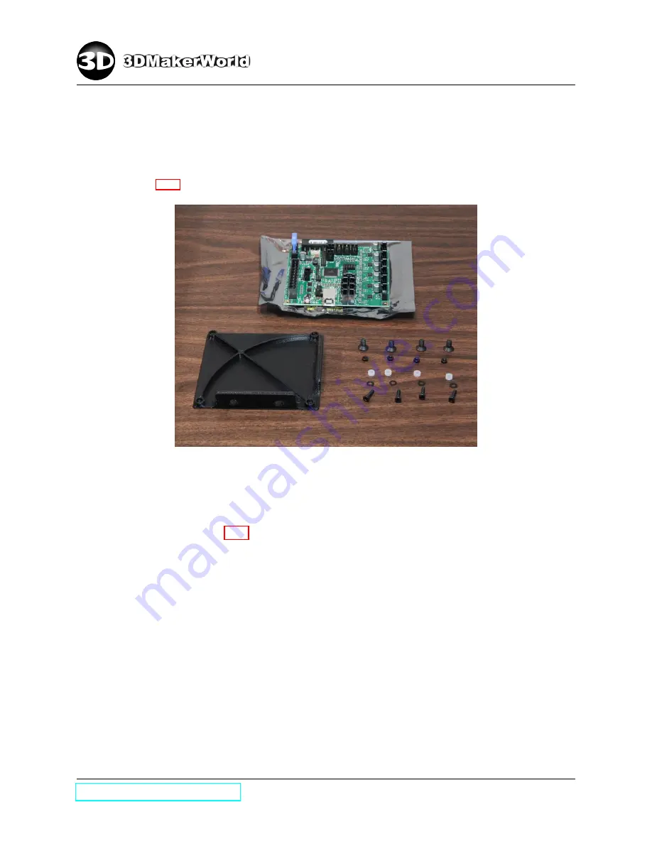
Parts for the installation of electronics onto the mount plate are shown in Fig-
ure 3.17.

Figure 3.17: Parts for the installation of electronics onto the mount plate (M3

×

12 SHS (

×

4),

M3 washer (

×

4), M3

×

3 spacer (

×

4), M3 nut (

×

4), M5

×

10 FHS (

×

4))

Install the electronics onto the mount plate following the same orientation as
shown in Figure 3.18. Four nuts fit into the nut housings on the bottom of mount
plate, and the spacers fit between the electronics and the mount plate.

http: // 3dmakerworld. com

33

Содержание Artifex 2

Страница 1: ...The Build Instructions of Artifex 2 Desktop 3D Printer http 3dmakerworld com Document date March 5 2015 Check website for latest update ...

Страница 2: ...Parts and Tools 22 3 2 Assembly Steps 23 3 2 1 Assembling lower frame 23 3 2 2 Installing power supply unit PSU 28 3 2 3 Installing electronics board 33 3 2 4 Installing Y axis components 37 3 2 5 Installing front panel 43 4 Upper Frame and Components 44 4 1 Required Parts and Tools 44 4 2 Assembly Steps 45 4 2 1 Assembling aluminum extrusions 45 4 2 2 Assembling X axis frame 54 4 2 3 Installing X...

Страница 3: ...ling three point bed leveling system 85 6 2 4 Installing heat spreader and glass top 86 6 2 5 Installing Y axis belt clamp 88 6 2 6 Installing Y axis belt 90 7 Wiring and Finishing Up 93 7 1 Required Parts and Tools 93 7 2 Assembly Steps 94 7 2 1 Installing mechanical endstops 94 7 2 2 Managing cables using spiral wraps 97 7 2 3 Installing extruder cable harness 101 7 2 4 Installing LCD controller...

Страница 4: ...oller with SD card read and other fine improvements The Artifex 2 offers both single and dual extruder models Figure 1 1 The design of Artifex 2 3D Printer is open to the public under the Creative Commons Attribution ShareAlike 3 0 Unported license CC BY SA 3 0 Figure 1 1 The Artifex 2 3D printer 1 1 Key Features and Sample Prints The key features of Artifex 2 3D printer include Flexible Material ...

Страница 5: ...e some sample prints made with the Artifex 2 3D printers Please check more sample prints and printing videos at our website Figure 1 2 Recreus sandals thing 404014 printed by Artifex 2 Figure 1 3 Giant hollow two color world thing 15658 printed by Artifex 2 Duo http 3dmakerworld com 6 ...

Страница 6: ... Yoda bust thing 14104 printed by Artifex 2 Figure 1 5 The T Rex skull thing 308335 printed by Artifex 2 1 2 Specifications The technical specifications of Artifex 2 3D printers are listed in Figure 1 6 http 3dmakerworld com 7 ...

Страница 7: ...1 INTRODUCTION Figure 1 6 The technical specifications of Artifex 2 http 3dmakerworld com 8 ...

Страница 8: ... before any service or trou bleshooting operation Always discharge yourself by touching a grounded source before touching the electron ics Never leave flammable materials near printer Place the printer in a well ventilated area for printing with ABS filaments 1 4 Acknowledgements First we would like to thank Maxbot for his design of MendelMax 2 which is arguably one of the most compact desktop 3D ...

Страница 9: ...ers in the reprap and other 3D printing communities for all the inspiration and support 1 5 Overview of Chapters The packing list will be provided in Chapter 2 Chapter 2 7 will cover the build process of Artifex 2 Single extruder in five different sections lower frame upper frame extruder heated build platform and wiring sections Chapter 8 will highlight the difference in the build process of Arti...

Страница 10: ...o right BHS FHS and SHS 4 420mm Aluminum extrusion 1 420mm Aluminum extrusion M5 tapped on one end 5 340mm Aluminum extrusion 4 340mm Aluminum extrusion M5 tapped on both ends 1 340mm Aluminum extrusion M5 tapped on both ends and a through hole drilled in the middle 1 270mm Aluminum extrusion 1 340mm X axis rail 1 270mm X axis rail 3 X axis carriage 1 Y axis rail 4 Y axis carriage 2 Z axis precisi...

Страница 11: ...D M3 25mm FHS 9 S 12 D M3 25mm SHS 2 D M3 20mm FHS 6 S 8 D M3 18mm FHS 6 S 8 D M3 16mm FHS 4 M3 12mm SHS 8 M3 10mm BHS 6 M3 8mm BHS 7 M3 8mm SHS 10 M3 6mm BHS 2 M3 6mm FHS 26 S 34 D M3 nut 6 M3 locknut 10 M3 T nut 4 M3 3mm spacer 27 S 30 D M3 washer 7 M3 fender washer 6 M2 10mm SHS 6 M2 nut 6 Section of spiral wrap 6 Zip tie 1 S 2 D Filament guide tube 2 2 Electronics Parts 4 NEMA17 stepper motor ...

Страница 12: ... M4 SHS 2 5mm hex screw driver M4 FHS M3 SHS 2mm hex screw driver M3 BHS FHS GT2 pulley set screw shaft coupler set screw 1 5mm hex key M2 SHS Y axis carriage 0 9mm hex key filament drive gear set screw not needed in the build process 8mm wrench M5 thin nut 5 5mm wrench M3 nut Tweezer removing melt filaments from the nozzle not needed in the build process 0 1mm feeler gauge bed leveling not needed...

Страница 13: ...2 PACKING LIST Figure 2 2 Artifex 2 tool set Figure 2 3 10 pieces of 0 08mm 3mil Kapton films 250x320mm http 3dmakerworld com 14 ...

Страница 14: ... Figure 2 4 2 4 1 Lower Frame 100 YEndFront 101 FrontPanel 102 LowerVertexFrontLeft 103 LowerVertexFrontRight same as 102 104 YMotorMount 105 PSUFanDuct 106 PSUMountBottomFront 107 HBPCableFixture 108 ElectronicsTopCover 109 ElectronicsMount 110 PSUCover 111 PSUMountBottomRear 112 LowerVertexRearLeft 113 PowerPanel 114 YEndRear 115 YIdlerMount 116 YEndStopMount 117 PSUCableFixture same as 107 118 ...

Страница 15: ...pperVertexBottomLeft 226 UpperVertexBottomRight 2 4 3 Extruder 300 S ExtruderMotorMount 300D D ExtruderMotorMountDuo 301 S FilamentDrive 301L D FilamentDriveLeft 301R D FilamentDriveRight 302 XBeltClampLeft 303 XBeltClampRight same as 302 304 S ExtruderFanMount 304 D ExtruderFanMountDuo 305 S ExtruderFanDuct 305L D ExtruderFanDuctLeft same as 305 305R D ExtruderFanDuctRight same as 305 2 4 4 HBP 4...

Страница 16: ...2 PACKING LIST 100 101 102 104 105 106 107 108 109 110 111 112 http 3dmakerworld com 17 ...

Страница 17: ...2 PACKING LIST 113 114 115 116 118 119 200 202 203 204 205 207 http 3dmakerworld com 18 ...

Страница 18: ...2 PACKING LIST 208 209 209R 210 211 215 216 227 220 221 222 223 http 3dmakerworld com 19 ...

Страница 19: ...2 PACKING LIST 224 225 226 300 300D 301 301L 301R 302 304 304D 305 http 3dmakerworld com 20 ...

Страница 20: ...2 PACKING LIST 400 404 405 406 500 501 502 Figure 2 4 List of printed parts http 3dmakerworld com 21 ...

Страница 21: ... Y axis carriage 1 Corner bracket 4 Rubber foot 1 GT2 timing belt pulley 3 605 bearing 1 M5 30mm SHS 2 M5 25mm FHS 5 M5 12mm BHS 63 M5 10mm FHS 8 M5 10mm SHS 1 M5 locknut 88 M5 T nut 9 M5 washer 4 M4 18mm FHS 4 M3 18mm FHS 4 M3 12mm SHS 3 M3 8mm SHS 2 M3 6mm FHS 10 M3 nut 4 M3 3mm spacer 4 M3 washer 3 M3 fender washer Electronics 1 NEMA17 stepper motor 1 RAMBo electronics board 1 24V 400W switchin...

Страница 22: ...M3 SHS 2mm hex screw driver M3 FHS GT2 pulley set screw 1 5mm hex key Y axis carriage Phillips screw driver self provided PSU cover scews Scissor self provided GT2 timing belt 3 2 Assembly Steps 3 2 1 Assembling lower frame Connect the Y axis rail support aluminum extrusion Allocate a 420mm aluminum extrusion with a M5 tapped hole on one side and a 340mm aluminum extrusion with a through hole dril...

Страница 23: ...0mm aluminum extrusion lines up with the screw head Then tight up the M5 12mm BHS screw Figure 3 2 Figure 3 2 Connecting aluminum extrusions Insert T nuts Lay out aluminum extrusions as shown in Figure 3 3 Four aluminum extru sions along the X axis are 340mm long with holes tapped on both sides and five aluminum extrusions along the Y axis are 420mm long http 3dmakerworld com 24 ...

Страница 24: ...rusion Top 2 0 3 0 Front 6 6 0 2 Rear 2 1 9 8 Bottom 0 0 0 3 Table 1 Number of M5 T nuts in slots of X axis aluminum extrusions on the lower frame Four Sides Left Top Aluminum Extrusion Left Bottom Aluminum Extrusion Right Top Aluminum Extrusion Right Bottom Aluminum Extrusion Y Axis Rail Support Top 5 0 8 0 4 Left 4 2 0 3 1 Right 0 0 6 2 1 Bottom 0 6 0 4 0 Table 2 Number of M5 T nuts in slots of ...

Страница 25: ... Similarly install the front right lower vertex with the bottom right and bottom front aluminum extrusions Install the front top aluminum extrusion between two front lower vertices Fig ure 3 5 Figure 3 5 Installing the front top aluminum extrusion M5 10 FHS 4 Rotate the assembled frame and install the rear vertices with bottom aluminum extrusions as shown in Figure 3 6 http 3dmakerworld com 26 ...

Страница 26: ...extrusion is connected with the front top aluminum extrusion via a corner bracket Notice that there is one M5 T nut in the rear side of the front top aluminum extrusion Figure 3 7 Installing top aluminum extrusions rear view M5 10 FHS 10 M5 10 SHS 2 Install the Y axis motor mount Connect the Y axis rail support aluminum extrusion with two front aluminum extru sions as shown in Figure 3 8 http 3dma...

Страница 27: ...to a upside down position and install four rubber feet on the the Y axis bottom aluminum extrusions right next to the vertices Figure 3 9 Figure 3 9 Installing rubber feet upside down M5 10 SHS 4 3 2 2 Installing power supply unit PSU Install the PSU fan duct Remove PSU cover screws and cut off the seal as shown in Figure 3 10 http 3dmakerworld com 28 ...

Страница 28: ...fan screws M5 25 FHS 2 Use two M5 25 FHS screws to hold the PSU fan duct PSU cover and PSU fan together The M5 screws will self tap into the plastics Hold the fan and fan duct together whiling tightening the screws Close the PSU cover place the cover screws and tighten them up Figure 3 12 shows the finished PSU with installed PSU fan duct http 3dmakerworld com 29 ...

Страница 29: ...3 12 Installed PSU fan duct Mount PSU Mount PSU to the bottom of lower frame as shown in Figure 3 13 Figure 3 13 Mounting PSU to lower frame upside down rear view M4 18 FHS 4 M5 10 FHS 4 Install the PSU top cover http 3dmakerworld com 30 ...

Страница 30: ... assembly over Place the PSU top cover as shown in Figure 3 14 and push it down to position Figure 3 14 Installation of PSU top cover Install the power panel Parts for the installation of power panel are shown in Figure 3 15 http 3dmakerworld com 31 ...

Страница 31: ... power panel M3 6 FHS 2 M3 nut 2 M5 10 FHS 4 Two M3 nuts for the AC receptacle fit into the nut housings on the back of panel and the power switch is a push in fit type Figure 3 16 shows the installed power panel Figure 3 16 Installed power panel http 3dmakerworld com 32 ...

Страница 32: ...re 3 17 Figure 3 17 Parts for the installation of electronics onto the mount plate M3 12 SHS 4 M3 washer 4 M3 3 spacer 4 M3 nut 4 M5 10 FHS 4 Install the electronics onto the mount plate following the same orientation as shown in Figure 3 18 Four nuts fit into the nut housings on the bottom of mount plate and the spacers fit between the electronics and the mount plate http 3dmakerworld com 33 ...

Страница 33: ...ate M3 12 SHS 4 M3 washer 4 M3 3 spacer 4 M3 nut 4 Install the electronics assembly onto the bottom of lower frame as shown in Fig ure 3 19 Figure 3 19 Mounting electronics assembly onto the lower frame upside down rear view M5 10 FHS 4 Install the top cover http 3dmakerworld com 34 ...

Страница 34: ...cover and the fan guard outside of the cover Figure 3 20 Parts for the installation of electronics cooling fan M3 18 FHS 4 M3 nut 4 Install the electronics top cover onto the lower frame using two M5 10 FHS screws Notice that there are two M5 T nuts on the corner of the electronics top cover Figure 3 21 For RAMBo electronics V1 2 and later versions please install the fan on the outside of the elec...

Страница 35: ...stalling the electronics top cover M5 10 FHS 2 Install the USB panel Turn the frame around and install the USB panel onto the lower frame in the rear Figure 3 22 Figure 3 22 Installing the USB panel rear view M5 10 FHS 4 http 3dmakerworld com 36 ...

Страница 36: ...he support aluminum ex trusion Figure 3 23 Then mount the Y axis rail onto the aluminum extrusion using four M5 12 BHS screws Figure 3 23 Aligning screw holes on the Y axis rail with T nuts rear view M5 12 BHS 4 M5 washer 4 Slide four Y axis carriages onto the rail and install the front and rear Y ends as shown in Figure 3 24 http 3dmakerworld com 37 ...

Страница 37: ...s of Y axis rail and Y ends Figure 3 25 Joint details of Y axis rail and Y ends left rear end right front end Adjust the fitting clearance of Y axis carriages To reduce the vibration during high speed printing the Artifex 3D Printer uses carriages with adjustable clearance for Y axis motion The fitting clearance can be adjusted by tightening or loosing the set screw on the side of the carriage usi...

Страница 38: ...e movement Balance the clearance of all carriages for them to have similar smoothness while sliding on the rail Figure 3 26 Adjusting the fitting clearance of Y axis carriages Install Y axis idler Parts for the installation of Y axis idler are shown in Figure 3 27 http 3dmakerworld com 39 ...

Страница 39: ...locknut M5 washer 5 The assembly details are shown in Figure 3 28 The order of hardware in the cen ter assembly is locknut ABS washer bearings washer ABS washer M5 30 Notice that the printed idler is oriented to have the side with rounded corners on the bottom Figure 3 28 Assembling the Y axis idler http 3dmakerworld com 40 ...

Страница 40: ...9 The idler has its rounded corners on the bottom Figure 3 29 Installing the Y axis idler assembly rear view Install Y axis motor Parts for the installation of Y axis motor are shown in Figure 3 30 Figure 3 30 Parts for the installation of Y axis motor M3 8 SHS 3 M3 fender washer 3 http 3dmakerworld com 41 ...

Страница 41: ...on the motor shaft Figure 3 31 Attaching the Y axis GT2 pulley Install the Y axis motor onto the motor mount as shown in Figure 3 32 The motor is oriented to have its cable port towards the front top of the printer Slide the motor away from the front inside the mounting holes to leave room for tightening up the Y axis belt in a later step http 3dmakerworld com 42 ...

Страница 42: ...32 Mounting the Y axis motor side view 3 2 5 Installing front panel Install the front panel onto the front of lower frame using eight M5 10 FHS screws Fig ure 3 33 Figure 3 33 Installing the front panel M5 10 FHS 8 http 3dmakerworld com 43 ...

Страница 43: ...cision shaft 2 Z axis lead screw with Delrin nut 4 10mm bronze bushing 2 Z axis shaft coupler 1 Z axis zeroing spring 3 605 bearing 1 GT2 timing belt pulley 1 M5 30mm SHS 1 M5 18mm SHS 18 M5 14mm FHS 37 M5 10mm FHS 10 M5 10mm SHS 1 M5 nut 11 M5 locknut 46 M5 T nut 3 M5 washer 6 M3 25mm SHS 8 M3 10mm BHS 4 M3 8mm SHS 10 M3 6mm BHS 6 M3 locknut 10 M3 T nut 14 M3 washer 4 M3 fender washer Electronics...

Страница 44: ... hex screw driver M5 SHS 3mm hex screw driver M5 FHS 2 5mm hex screw driver M3 SHS 2mm hex screw driver M3 BHS GT2 pulley set screw shaft coupler set screw 5 5mm wrench M3 locknut Metric tape self provided positioning Z axis upright aluminum extrusions lev eling X axis rails Power drill optional self provided pre fitting lead screws into Delrin nuts Paper towel self provided wiping oil off shafts ...

Страница 45: ...ling corner bracket to the upright Z axis aluminum extrusion M5 10 SHS Connect the upright Z axis aluminum extrusion to the lower frame as shown in Figure 4 3 The front of Z axis aluminum extrusion is 128 5mm away from the front of top rear aluminum extrusion on the lower frame Notice that there are two M5 T nuts in the channel of left top aluminum extrusion in front of the upright Z axis aluminum...

Страница 46: ...ht Z axis aluminum extrusion on the right side and keep two M5 T nuts in the channel of right top aluminum extrusion in front of the upright Z axis aluminum extrusion Figure 4 4 shows the finished upright Z axis frame Figure 4 4 Installed upright Z axis aluminum extrusions Install the top horizontal frame http 3dmakerworld com 47 ...

Страница 47: ...rails in Table 3 and rear aluminum extrusions in Table 4 will be needed in later sections of this chapter Notice that there is already one M5 T nut in the rear side of left front and right front aluminum extrusions respectively for the installation of corner brackets Four Sides Top Horizontal Alu minum Extrusion X Axis Front Rail Aluminum Extrusion X Axis Rear Rail Aluminum Extrusion Top 1 6 M3 4 ...

Страница 48: ...t 2 1 4 0 Right 1 2 0 3 Rear 2 3 4 4 Table 4 Number of M5 T nuts in slots of Z axis aluminum extrusions on the upper frame Note Please refer to Table 6 in Chapter 8 for Artifex 2 Duo Figure 4 6 Connecting two aluminum extrusions in the top right hand corner M5 10 SHS Install Z axis motor mounts Instal the left Z axis motor mount as shown in Figure 4 7 http 3dmakerworld com 49 ...

Страница 49: ...HS Similarly install another Z axis motor mount on the right hand side Install Z axis supporting aluminum extrusions Install the top left vertex for Z axis supporting aluminum extrusion as shown in Figure 4 8 Figure 4 8 Installing the top left vertex rear view M5 10 FHS 3 http 3dmakerworld com 50 ...

Страница 50: ...e end against the bottom left vertex and insert M5 T nuts per list in Table 4 front 1 left 4 right 0 rear 4 Push the aluminum extrusion into the housing slot on the top and bottom vertices and tighten it up using M5 10 FHS screws You may need to adjust the top or bottom vertex to let the aluminum extrusion to fit in Similarly install the Z axis supporting aluminum extrusion on the right hand side ...

Страница 51: ...alling Z axis supporting aluminum extrusions rear view M5 10 FHS 8 Install Z axis brackets Allocate the left Z axis bracket Vertically align holes on the bracket with T nuts in the slots of aluminum extru sions Figure 4 11 http 3dmakerworld com 52 ...

Страница 52: ...ith T nuts side view M5 10 FHS 3 Loosely insert the top screw move the bracket up to insert two screws on the bottom and then tighten up all screws Figure 4 12 Figure 4 12 Installed left Z axis bracket side view Install the right Z axis bracket in a similar way http 3dmakerworld com 53 ...

Страница 53: ...d are shown in Figure 4 13 Two 10mm bronze bushings are installed on the top and bottom of shaft opening Figure 4 13 Parts for assembling the left X end 605 bearing 3 M5 30 SHS M5 locknut M5 washer 2 Assemble the X axis idler in the order of locknut ABS washer bearings washer M5 30 Figure 4 14 http 3dmakerworld com 54 ...

Страница 54: ...he right X end Parts for assembling the right X end are shown in Figure 4 15 Two 10mm bronze bushings are installed on the top and bottom of shaft opening Figure 4 15 Parts for assembling the right X end M5 nut Z axis zeroing spring M5 washer M5 18 SHS http 3dmakerworld com 55 ...

Страница 55: ...towards the nut opening If needed open the entry up using a craft knife to fit the nut in Be careful of the sharp blade of the knife Figure 4 16 Assembled right X end bottom view Assemble X axis frame Parts for assembling the X axis frame are shown in Figure 4 17 The front X axis aluminum extrusion is 340mm long and the rear is 270mm long Figure 4 17 Parts for assembling the X axis frame M5 14 FHS...

Страница 56: ...Figure 4 18 Figure 4 18 Aligning the X axis aluminum extrusions with X ends Secure the aluminum extrusions on the bottom of X ends using eight M5 14 FHS screws Figure 4 19 Figure 4 19 Assembled X axis frame bottom view M5 14 FHS 8 4 2 3 Installing X axis rails and carriages Parts for assembling X axis rail are shown in Figure 4 20 Note that M3 T nuts are used here to mount X axis rails http 3dmake...

Страница 57: ...ns Center the rails on the top of aluminum extrusions Insert carriages into the channels of X axis rails Figure 4 21 two in the front and one in the rear Figure 4 21 Inserting X axis carriages 4 2 4 Installing Z axis shafts Mount Z axis shafts Parts for the installation of Z axis shafts are shown in Figure 4 22 http 3dmakerworld com 58 ...

Страница 58: ...f the shaft surface using paper towel Note The bronze bushings installed in X axis ends have 5 adjustable angle Gently twist the bushing using the shaft to adjust the alignment angle so the shaft can slide between top and bottom bushings smoothly Figure 4 23 Pre fitting shafts through X end bushings Install the left shaft bottom mount as shown in Figure 4 6 Similarly install the right shaft bottom...

Страница 59: ...shaft bottom mounts as shown in Figur 4 6 Figure 4 25 Positioning X axis assembly Insert shafts through bushings from the top and secure the shafts on both ends using shaft clasps as shown in Figure 4 26 The M5 locknuts fit in the nut housings of the motor mount on the top and the shaft mount on the bottom http 3dmakerworld com 60 ...

Страница 60: ...in Figure 4 27 Hold the X axis assembly on both ends and carefully slide the assembly up and down Keep the assembly level while moving it and wipe oil off the shaft surface using paper towel Repeat the above step a few times till the movement is smooth Then tight up the screws on shaft bottom mounts at their new positions Note The new positions allow shafts to move freely Do not push the shaft bot...

Страница 61: ...stalling Z axis motors Parts for the installation of Z axis motors are shown in Figure 4 28 Figure 4 28 Parts for the installation of Z axis motors M3 10 BHS 8 M3 washer 8 Install the left Z axis motor onto the motor mount as shown in Figure 4 29 Similarly install the right Z axis motor http 3dmakerworld com 62 ...

Страница 62: ... Parts for the installation of lead screws are shown in Figure 4 30 Screw the Delrin nuts onto the lead screws from the bottom and keep both Delrin nuts at the same level on the lead screws as shown in the figure Figure 4 30 Parts for the installation of lead screws M10 rubber washer 2 M3 25 SHS 6 M3 washer 6 M3 locknut 6 http 3dmakerworld com 63 ...

Страница 63: ... Figure 4 31 Inserting lead screws through X axis assembly Insert the left lead screw into the shaft coupler till the lead screw contacts the motor shaft Release the shaft coupler from the motor shaft and slide the coupler downwards against the lead screw Then tight up all set screws on the shaft coupler to connect the lead screw and the motor shaft Make sure one set screw on the shaft coupler mat...

Страница 64: ...d and the Delrin nut together as shown in Figure 4 33 Figure 4 33 Connecting the left X end and the Delrin nut M3 25 SHS 3 M3 washer 3 M3 locknut 3 Similarly install the right lead screw Then measure the distance between the X axis assembly and the bottom of left and right Z axis motor mounts Manually turn the http 3dmakerworld com 65 ...

Страница 65: ...the distances on both ends to level the X axis assembly with the printer frame Figure 4 34 Figure 4 34 Leveling the X axis assembly 4 2 7 Installing X axis motor Parts for the installation of X axis motor are shown in Figure 4 35 http 3dmakerworld com 66 ...

Страница 66: ...ttach the GT2 belt pulley onto the motor shaft as shown in Figure 4 36 Make sure one set screw on the GT2 pulley mates the flat spot on the motor shaft Figure 4 36 Attaching GT2 pulley onto X axis motor shaft Mount the X axis motor onto the right X end as shown in Figure 4 37 Slide the motor http 3dmakerworld com 67 ...

Страница 67: ...he right X end 4 2 8 Mounting 3DMakerWorld tag Mount the 3DMakerWorld tag in the center of top horizontal bar using two M5 10 FHS screws Figure 4 38 Figure 4 38 Mounting the 3DMakerWorld tag M5 10 FHS 2 4 2 9 Installing spool holder and filament guide mount Parts for the installation of spool holder and filament guide mount are shown in Fig ure 4 39 http 3dmakerworld com 68 ...

Страница 68: ...filament guide mount M5 10 FHS 5 M5 14 FHS 2 M5 locknut 2 Install the spool holder and the filament guide mount onto the printer frame as shown in Figure 4 40 Use two M5 14 FHS screws and two M5 locknuts to mount the spool holder and the spool holder mount together http 3dmakerworld com 69 ...

Страница 69: ...4 UPPER FRAME AND COMPONENTS Figure 4 40 Installing the spool holder and the filament guide mount rear view http 3dmakerworld com 70 ...

Страница 70: ...3 16mm FHS 6 M3 8mm BHS 12 M3 nut 9 M3 washer Electronics 1 Geared extruder motor with filament drive gear mounted 1 Hot end assembly 2 40mm 24V cooling fan 2 40mm fan guard Printed parts 300 ExtruderMotorMount 301 FilamentDrive 302 XBeltClampLeft 303 XBeltClampRight 304 ExtruderFanMount 305 ExtruderFanDuct Required tools 3mm hex screw driver M4 SHS 2 5mm hex screw driver M3 SHS 2mm hex screw driv...

Страница 71: ...n of extruder motor mount are shown in Figure 5 1 Figure 5 1 Parts for the installation of extruder motor mount M3 8 BHS 6 M3 washer 6 Install the motor mount onto X axis rail carriages using four M3 8 BHS screws in the front and two in the rear Figure 5 2 Make sure to tight all screws evenly http 3dmakerworld com 72 ...

Страница 72: ...r the far right screw Figure 5 3 Slide the extruder motor mount back and forth a few times along the X axis rails Tight up the far left screw while keeping the rail at its new position and loose the far right screw Slide the extruder motor mount back and forth a few times along the X axis rails Tight up all screws while keep the rial at its new position http 3dmakerworld com 73 ...

Страница 73: ...ail for tightness adjustment Mount extruder motor Parts for mounting the extruder motor are shown in Figure 5 4 Figure 5 4 Parts for mounting the extruder motor M4 20 SHS 2 M4 locknut 2 Mount the extruder motor as shown in Figure 5 5 http 3dmakerworld com 74 ...

Страница 74: ...embling and installing filament drive Assemble filament drive Parts for assembling the filament drive are shown in Figure 5 6 Figure 5 6 Parts for assembling the filament drive M4 18 SHS M4 locknut M4 14 shoul der screw 625 bearing M4 nut http 3dmakerworld com 75 ...

Страница 75: ...end assembly on the right hand side to work with the wiring set up in a later step After the assembly please feed a section of 1 75mm filament into the hot end from the top and make sure the filament can reach the hot end smoothly Figure 5 7 Assembled filament drive front and back Install filament drive Install the filament drive to the extruder motor using three M3 25 SHS screws Figure 5 8 http 3...

Страница 76: ...er cooling fans Parts for assembling and installing extruder cooling fans are shown in Figure 5 9 Figure 5 9 Parts for assembling and installing extruder cooling fans M3 16 FHS 2 M3 30 FHS 2 M3 25 FHS 2 M3 18 FHS 2 M3 nut 8 Assemble and install extruder cooling fans as shown in Figure 5 10 http 3dmakerworld com 77 ...

Страница 77: ...on of X axis belt are shown in Figure 5 11 Figure 5 11 Parts for the installation of X axis belt M3 16 FHS 4 M3 nut 4 Install the X axis belt clamp onto the extruder motor mount as shown in Figure 5 12 Two M3 nuts are inserted into the nut housings on the bottom of extruder motor mount http 3dmakerworld com 78 ...

Страница 78: ...e belt on another end Figure 5 13 Before tightening the clamps straight the belt up and cut off extra length on the end Note The belt only needs to be straight up in this step and it will be tightened up by sliding the X axis motor in a later step Figure 5 13 Installing the X axis GT2 timing belt Adjust the GT2 pulley on the X axis motor shaft to align the GT2 timing belt from end to end Figure 5 ...

Страница 79: ...14 Aligning X axis GT2 timing belt Loose the mounting screws on the X axis motor While holding the motor pull it to the right along the mounting slots to tighten up the belt Then fasten all screws http 3dmakerworld com 80 ...

Страница 80: ...t 3 M5 thin nut 1 M5 locknut 7 M5 thumb nut 4 Zip tie Electronics 1 24V HBP heater attached to HBP heat spreader Printed parts 400 HBPCornerLeftFront 401 HBPCornerRightFront 402 HBPCornerLeftRear 403 HBPCornerRightRear 404 HBPSpringHolder 405 HBPCableStrainRelief 406 YBeltClamp Required tools 4mm hex screw driver M6 BHS M5 SHS 3mm hex screw driver M5 BHS 2mm hex screw driver GT2 pulley set screw 8...

Страница 81: ...ttom plate on the top of Y axis rail carriages The edge with one screw hole is on the left and the edge with two screw holes is on the right Then align the screw holes on the plate with the screw holes on the Y axis rail carriages Insert M6 10 BHS screws and tighten them up evenly When fastening screws slide the plate along the Y axis rail back and force to ensure a smooth but not loose move ment ...

Страница 82: ...or assembling the HBP main plate are shown in Figure 6 3 Figure 6 3 Parts for assembling the HBP main plate M5 20 bolt 4 M5 thumb nut 4 M5 20 SHS 3 M5 thin nut 3 Heater Support Spring M5 10 BHS M5 nut Install the HBP corner to the main plate as shown in Figure 6 4 The head of M5 20 http 3dmakerworld com 83 ...

Страница 83: ... 20 bolt M5 thumb nut A sprint is placed in the center of main plate to achieve good contact between the heat spreader and the glass top The M5 nut is inserted into the nut housing on the top and the M5 10 BHS screw is inserted from the bottom Figure 6 5 Figure 6 5 Installing HBP heater support spring M5 10 BHS M5 nut http 3dmakerworld com 84 ...

Страница 84: ...2 3 Installing three point bed leveling system Place the bed leveling springs over the screw holes along the edge of HBP bottom plate Figure 6 7 Figure 6 7 Placing the three point bed leveling springs Place the HBP main plate on the top of HBP bottom plate Pass the bed leveling screws on the main plate through the springs and mounting holes on the bottom plate and secure the screws using M5 thumb ...

Страница 85: ...nstallation hardware for the HBP cable strain relief In your Artifex package the heater is pre mounted on the bottom of the heat spreader and the heater and thermistor connectors are pre installed Figure 6 9 HBP heat spreader glass top and HBP cable strain relief M5 12 BHS M5 locknut Mount the HBP cable strain relief onto the HBP main plate as shown in Figure 6 10 http 3dmakerworld com 86 ...

Страница 86: ...stalling the HBP cable strain relief rear view Loose the thumb screw on the HBP corner Fit the heat spreader and the glass top into the slot of HBP corner Push the HBP corner towards the center to secure the heat spreader and the glass top in place Then tighten up the thumb screw on the HBP corner Figure 6 11 http 3dmakerworld com 87 ...

Страница 87: ...corner 6 2 5 Installing Y axis belt clamp Parts for the installation of Y axis belt clamp are shown in Figure 6 12 Figure 6 12 Parts for the installation of Y axis belt clamp M6 16 BHS 4 M6 lock washer 4 Carefully flip the printer bottom up and lay it down against the Z axis supporting http 3dmakerworld com 88 ...

Страница 88: ...ide down towards the rear when the printer is flipped up Figure 6 13 Flipping up the printer bottom up rear view Place the HBP heater cable between the Y axis belt clamp and the HBP bottom plate and mount the Y axis belt clamp onto the pair of Y axis rail carriages on the bottom Figure 6 14 http 3dmakerworld com 89 ...

Страница 89: ...ation of Y axis belt are shown in Figure 6 15 Figure 6 15 Parts for the installation of Y axis belt Adjust the GT2 pulley on the Y axis motor shaft to align it to the center of aluminum extrusion as shown in Figure 6 16 Note Make sure one set screw on the GT2 pulley mates the flat spot on the motor shaft http 3dmakerworld com 90 ...

Страница 90: ... mounting slots towards the rear of printer as shown in Figure 6 17 Figure 6 17 Positioning Y axis motor before installing the Y axis belt rear view Cut the GT2 timing belt loop to one straight line section Secure one end of the belt to the Y axis belt clamp using two zip ties as shown in Figure 6 18 Pass the belt around http 3dmakerworld com 91 ...

Страница 91: ...p and it will be tightened up by sliding the Y axis motor in the next step Figure 6 18 Installing Y axis belt onto the Y axis belt clamp rear view Carefully flip the printer up to its upright position Loose screws on the Y axis motor and pull the motor towards the front of the printer to tighten up the Y axis belt Then tighten up screws to secure the Y axis motor http 3dmakerworld com 92 ...

Страница 92: ... wiring Printed parts 107 HBPCableFixture 116 YEndStopMount 117 PSUCableFixture 201 ExtruderCableFixtureTop 211 XEndStopCableFixture 212 ExtruderCableFixtureSideTop 213 XMotorCableFixture 214 ExtruderCableFixtureSideBottom 217 XEndStopMount 224 ZEndStopMount 500 LCDTopCover 501 LCDBackCover 502 LCDCableFixtureFront 503 LCDCableFixtureRear Required tools 3mm hex screw driver M5 FHS 1 5mm hex key M2...

Страница 93: ...hanical endstops Parts for the installation of mechanical endstops are shown in Figure 7 1 Figure 7 1 Parts for the installation of mechanical endstops M5 10 FHS 3 M2 10 SHS 6 M2 nut 6 Assemble X Y Z mechanical endstops as shown in Figure 7 2 http 3dmakerworld com 94 ...

Страница 94: ...X axis rear rail supporting aluminum extrusion The X axis mechanical endstop can slide left and right along the X axis to define the zero position of X axis Figure 7 3 Installing the X axis mechanical endstop assembly rear view Install the Y axis mechanical endstop assembly as shown in Figure 7 4 between the USB panel and the Y axis idler http 3dmakerworld com 95 ...

Страница 95: ...HING UP Figure 7 4 Installing the Y axis mechanical endstop assembly rear view Install the Z axis mechanical endstop assembly as shown in Figure 7 5 to the right upright Z axis aluminum extrusion http 3dmakerworld com 96 ...

Страница 96: ...ections of spiral wraps are provided in your Artifex package for cable management Figure 7 6 Figure 7 6 Sections of spiral wraps for cable management Wrap the X motor spiral wrap onto X axis motor cables as shown in Figure 7 7 insert the bottom section of the wrapped cables into the front slot of Z axis supporting http 3dmakerworld com 97 ...

Страница 97: ...aking off two mounting screws on the top Wrap the Y motor spiral wrap onto Y axis motor cables and Z axis endstop cables and insert the the wrapped cables into slots of aluminum extrusions on the lower frame The end of wrapped cables should reach the rear top aluminum extrusion on the lower frame Figure 7 8 Figure 7 8 Installing spiral wrap for Y axis motor cables and Z axis endstop cables left fr...

Страница 98: ...bles when they join together in the middle of left Z axis supporting aluminum extrusion Secure the joint using the XEndStopCableFixture 211 part and a M5 10 FHS screw The bottom section of cables are wrapped in a second piece of spiral wrap and fits in the slot of rear top aluminum extrusion on the lower frame Figure 7 9 Installing spiral wraps for left Z axis motor cables and X axis endstop cable...

Страница 99: ... rear view Wrap the right Z motor spiral wraps onto right Z axis motor cables and insert the wrapped cables into the left slot of right Z axis supporting aluminum extrusion Fig ure 7 11 Figure 7 11 Installing spiral wrap for right Z axis motor cables side view http 3dmakerworld com 100 ...

Страница 100: ...er motor Loose two fastening screws on the top of extruder motor mount fit the extruder cable harness into the cable channel and then tighten up the fastening screws of the extruder motor mount Secure the cable harness onto the top of filament drive using a zip tie Connect cables to other extruder components including hot end heater hot end thermistor print cooling fan F0 and filament drive coolin...

Страница 101: ...ure 7 13 Connecting extruder cables Mount the bottom section of extruder cable harness along the top horizontal aluminum extrusion and the right Z axis supporting aluminum extrusion as shown in Figure 7 14 http 3dmakerworld com 102 ...

Страница 102: ...AND FINISHING UP Figure 7 14 Mounting extruder cable harness side view M5 10 FHS 3 7 2 4 Installing LCD controller Parts for the installation of LCD controller are shown in Figure 7 15 http 3dmakerworld com 103 ...

Страница 103: ...CD controller M3 25 FHS 4 M3 nut 4 M5 10 FHS 4 Assemble the LCD controller as shown in Figure 7 16 Figure 7 16 Assembled LCD controller front and back M3 25 FHS 4 M3 nut 4 Insert the LCD adapter onto the electronics board as shown in Figure 7 17 http 3dmakerworld com 104 ...

Страница 104: ...D controller as shown in Figure 7 18 Note the cable labels match those shown in Figure 7 17 Figure 7 18 Connecting cables to LCD controller Install the LCD controller to the right side of printer frame as shown in Figure 7 19 Use two cable fixtures to keep LCD cables in place http 3dmakerworld com 105 ...

Страница 105: ...ector of filament drive cooling fan F1 Note Be careful of the wire polarity Figure 7 20 Connecting cables of electronics cooling fan to F1 connector Connect MOSFET connectros to electronics including connectors of hot end heater print cooling fan F0 filament drive cooling fan F1 electronics cooling fan and HBP heater Figure 7 21 http 3dmakerworld com 106 ...

Страница 106: ... cables to electronics as shown in Figure 7 22 Figure 7 22 Connecting thermistor cables to electronics white hot end thermistor T0 black HBP thermistor T2 Connect cables of X Y Z mechanical endstops as shown in Figure 7 23 Note All endstops are connected to the MIN positions http 3dmakerworld com 107 ...

Страница 107: ...SHING UP Figure 7 23 Connecting cables of X Y Z mechanical endstops Connect cables of all step motors as shown in Figure 7 24 Figure 7 24 Connecting cables of step motors red wire facing front http 3dmakerworld com 108 ...

Страница 108: ...es using a zip tie as shown in Figure 7 25 Figure 7 25 Closed electronics top cover after wire connection Cover the electronics cabling with the top cover as shown in Figure 7 26 Figure 7 26 Closing the electronics top cover rear view http 3dmakerworld com 109 ...

Страница 109: ...y cable harnesses Take off the power panel from the lower frame and connect power supply cables to the AC input receptacle and the power switch as shown in Figure 7 28 Then install the power panel back to the lower frame Figure 7 28 Connecting power supply cables to the AC input receptacle and the power switch green earth white neutral black live http 3dmakerworld com 110 ...

Страница 110: ...outputs and the three ports on the far right are AC inputs Then install the PSU cover back Figure 7 29 Connecting power supply cables to PSU input output ports rear view Connect DC power supply cables to the electronics power input port and secure the HBP heater cable to the printer frame as shown in Figure 7 30 Figure 7 30 Connecting DC power supply cables and securing HBP heater cable side view ...

Страница 111: ... harness onto the rear bottom aluminum extrusion on the lower frame as shown in Figure 7 31 After the installation carefully flip the printer up to its upright position Figure 7 31 Mounting the power supply cable harness bottom view M5 10 FHS 7 2 7 Finishing up Install the filament spool onto the spool holder as shown in Figure 7 32 http 3dmakerworld com 112 ...

Страница 112: ...to the extruder will be introduced in the User Manual Figure 7 33 Installing filament guide tube spool end and extruder end Congratulations You have finished building your Artifex 2 3D Printer Figure 7 34 provides the front left right and rear view of the assembled Artifex 2 3D Printer Take the chance to review the printer If you identify any missed or misplaced compo nents please go back to previ...

Страница 113: ...7 WIRING AND FINISHING UP instructions Front view Left view Right view Rear view Figure 7 34 Assembled Artifex 2 3D printer front left right and rear view http 3dmakerworld com 114 ...

Страница 114: ...uminum Extrusion X Axis Rear Rail Aluminum Extrusion Top 2 6 M3 4 M3 Front 4 0 0 Rear 3 0 1 Bottom 2 4 4 Table 5 Artifex 2 Duo Number of M5 M3 T nuts in slots of X axis aluminum extrusions on the upper frame Red different from Artifex 2 Four Sides Left Front Aluminum Extrusion Right Front Aluminum Extrusion Left Rear Aluminum Extrusion Right Rear Aluminum Extrusion Front 0 0 1 0 Left 2 1 4 0 Right...

Страница 115: ... 2 M4 locknut 2 M4 14 shoulder screw 2 625 bearing 2 M4 nut 2 M3 25 SHS 6 M3 washer 6 Figure 8 2 shows the extruder after connecting the motor and hotend cables Figure 8 2 Extruder of Artifex 2 Duo with motor and hotend cables Figure 8 3 shows the extruder after connecting the cooling fans http 3dmakerworld com 116 ...

Страница 116: ... DUO Figure 8 3 Extruder of Artifex 2 Duo with cooling fans M3 16 FHS 4 M3 20 FHS 2 M3 30 FHS 2 M3 25 FHS 4 M3 18 FHS 4 M3 nut 16 8 3 Overview Figure 8 4 shows the assembled Artifex 2 Duo http 3dmakerworld com 117 ...

Страница 117: ...8 ARTIFEX 2 DUO Figure 8 4 The assembled Artifex 2 Duo 3D printer http 3dmakerworld com 118 ...

Страница 118: ...rworld com contacts For updates of software documents and other technical support topics please visit us at http www 3dmakerworld com support Please follow the directions in the User Manual Fig 9 1 to learn how to use your Artifex 2 3D Printer Figure 9 1 The User Manual of Artifex 2 3D Printer Thanks for your purchase of 3DMakerWorld Artifex 2 3D Printer Enjoy your printing http 3dmakerworld com 1...

Отзывы: