
13
3D Systems, Inc
.
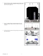
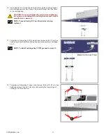
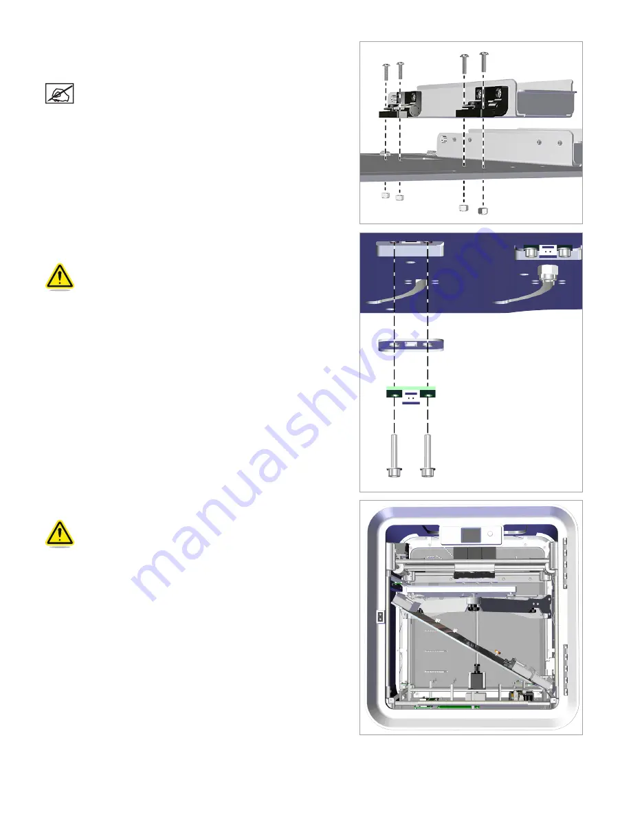
19.
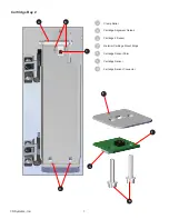
Place cartridge bay2 on top of the inner floor. Insert the four (4) 2.5
mm hex head screws through the lower hinges and the inner floor and
attach the four 7 mm nuts. Tighten the nuts.
NOTE: Proceed to step 21 if no other parts are being
replaced.
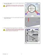
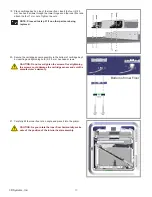
20. Secure the cartridge sensor assembly to the bottom of cartridge bay 2
by inserting and tightening both (2) 2.5 mm hex head screws.
CAUTION: Do not over-tighten the screws. Over-tightening
the screws could damage the cartridge sensor and void the
manufacturer’s warranty.
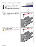
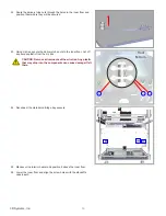
21.
Carefully tilt the inner floor at an angle and place it into the printer.
CAUTION: As you rotate the inner floor horizontally, make
note of the position of the interior heater assembly.
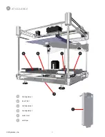
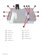
Bottom of Inner Floor


