TD_UserManual_SCALEREO-Desk_13xyyC
Rev. 1.4 / 25.02.2022
18
/ 29
4. Operation
4.1 Positioning of the specimens
Depending on the actual height of the specimens to be viewed under the microscope, the height-
adjustable camera/illumination head has to be brought into a suitable position.
To do this, use the turning device attached to the upper end of the rail. A scale on the front of
the rail shows you the ideal setting height for the respective specimen height.
•
For flat specimens (printed circuit boards, etc.), the camera/illumination head can re-
main in the lowest position.
=> Scale: Arrow pointing to “0”.
•
For tall specimens (e.g. parts of 15 cm height), the camera/illumination head should
be moved approx. 15 cm up
=> Scale: Arrow pointing to “15”.
Position the specimen centrally in the area under the camera.
4.2 Fundamental operating concept
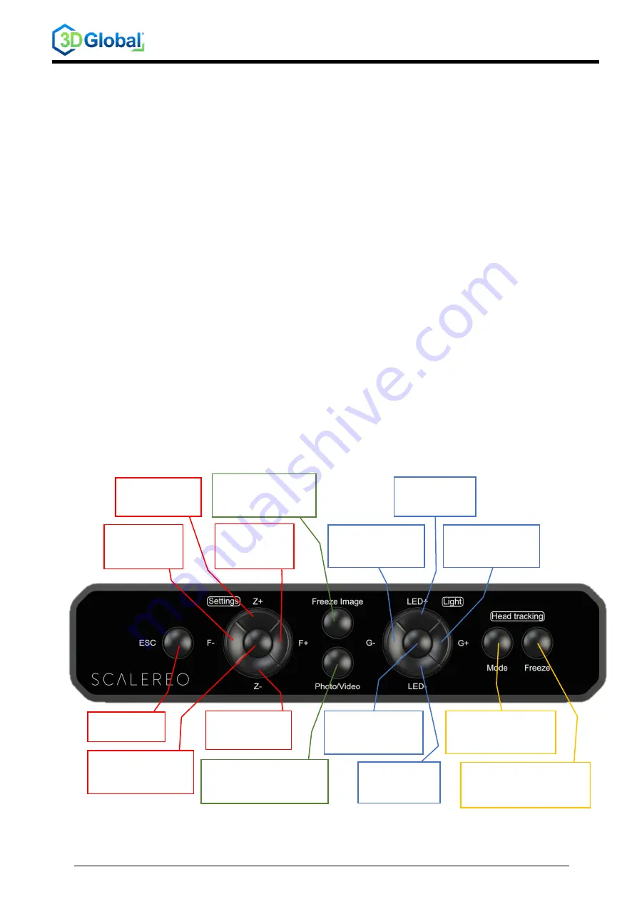
The whole system is controlled via the ControlBar. The ControlBar is designed in such a way
that it can be individually optimised for the respective working method and positioned directly at
the workstation. The buttons are mostly self-explanatory and intuitive to use.
Some of the buttons have different functions, depending on how long the buttons are pressed.
The diagram below shows the basic assignment of the keys; in the case of a possible double
assignment, the respective functions are marked with
•
SP
(short press < 0.5 s), or
•
LP
(long press ~1 s)
.
SP:
Autofocus
LP:
Zoom in
Focus out
Focus plane
up
Enter settings menu
Within the menu:
“Confirm”
Focus in
Focus plane
down
SP:
Autofocus
LP:
Zoom out
Quit current
menu
Pause / “freeze”
current image
SP:
Save image
(or STOP video recording)
LP:
START video recording
Increase
LED brightness
Decrease
camera GAIN
Increase
camera GAIN
Toggle between
different
lighting modes
Decrease
LED brightness
Toggle between
different head-
tracking modes
Pause / “freeze”
headtracking at
current position


