background image


2-3 

Figure 2-4 

Set port parameters 


3)  Turn on the switch. You will be prompted to press the Enter key if the switch successfully 

completes POST (power-on self test). The prompt appears after you press the Enter key. 

4)  You can then configure the switch or check the information about the switch by executing the 

corresponding commands. You can also acquire help by typing the ? character. Refer to related 
parts in this manual for information about the commands used for configuring the switch.  

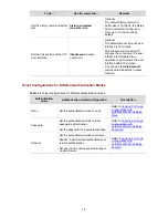
Console Port Login Configuration 

Common Configuration 

Table 2-2 

Common configuration of console port login 

Configuration 

Remarks 

Baud rate 

Optional 
The default baud rate is 19,200 bps. 

Check mode 

Optional 
By default, the check mode of the console port is set to 

“none”, which means no check bit. 

Stop bits 

Optional 
The default stop bits of a console port is 1. 

Console port 

configuration 

Data bits 

Optional 
The default data bits of a console port is 8. 

AUX user interface 

configuration 

Configure the 

command level 

available to the 

users logging in to 

the AUX user 

interface 

Optional 
By default, commands of level 3 are available to the 

users logging in to the AUX user interface. 

Terminal 

configuration 

Make terminal 

services available 

Optional 
By default, terminal services are available in all user 

interfaces 

Содержание Switch 4500 Family

Страница 1: ...ation Guide Switch 4500 26 Port Switch 4500 50 Port Switch 4500 PWR 26 Port Switch 4500 PWR 50 Port Product Version V03 03 00 Manual Version 6W101 20090811 www 3com com 3Com Corporation 350 Campus Dri...

Страница 2: ...mercial license for the Software Technical data is provided with limited rights only as provided in DFAR 252 227 7015 Nov 1995 or FAR 52 227 14 June 1987 whichever is applicable You agree not to remov...

Страница 3: ...ding table management and the related configuration 12 Auto Detect Introduces auto detect function and the related configuration 13 MSTP Introduces STP MSTP and the related configuration 14 Routing Pr...

Страница 4: ...pplications and the related configuration 38 Access Management Introduces Access Management and the related configuration 39 Appendix Lists the acronyms used in this manual Conventions The manual uses...

Страница 5: ...ollowing Manual Description 3Com Switch 4500 Family Command Reference Guide Provide detailed descriptions of command line interface CLI commands that you require to manage your switch 3Com Switch 4500...

Страница 6: ...sword 2 7 Configuration Procedure 2 7 Configuration Example 2 8 Console Port Login Configuration with Authentication Mode Being Scheme 2 9 Configuration Procedure 2 9 Configuration Example 2 10 3 Logg...

Страница 7: ...Disabling the WEB Server 6 3 7 Logging In Through NMS 7 1 Introduction 7 1 Connection Establishment Using NMS 7 1 8 Configuring Source IP Address for Telnet Service Packets 8 1 Overview 8 1 Configurin...

Страница 8: ...CLI Configuration Web based Network Management Interface Logging In Through the Web based Network Management Interface Network Management Station Logging In Through NMS Introduction to the User Inter...

Страница 9: ...s under this user interface z The user interface assigned to a user depending on the login mode and login time A user interface can be used by one user at one time however the user interface is not de...

Страница 10: ...n shell text Optional By default no banner is configured Set a system name for the switch sysname string Optional Enable copyright information displaying copyright info enable Optional By default copy...

Страница 11: ...g in to Switch 4500 through its console port only Table 2 1 lists the default settings of a console port Table 2 1 The default settings of a console port Setting Default Baud rate 19 200 bps Flow cont...

Страница 12: ...e following assumes that you are running Windows XP and perform the configuration shown in Figure 2 2 through Figure 2 4 for the connection to be created Normally both sides that is the serial port of...

Страница 13: ...2 2 Common configuration of console port login Configuration Remarks Baud rate Optional The default baud rate is 19 200 bps Check mode Optional By default the check mode of the console port is set to...

Страница 14: ...x shown in Figure 2 4 Follow these steps to set common configuration of console port login To do Use the command Remarks Enter system view system view Enter AUX user interface view user interface aux...

Страница 15: ...peration is performed in the user interface within 10 minutes You can use the idle timeout 0 command to disable the timeout function Console Port Login Configurations for Different Authentication Mode...

Страница 16: ...By default users logging in through the console port AUX user interface are not authenticated Configuration Example Network requirements Assume that the switch is configured to allow users to log in t...

Страница 17: ...onsole port to 19 200 bps Sysname ui aux0 speed 19200 Set the maximum number of lines the screen can contain to 30 Sysname ui aux0 screen length 30 Set the maximum number of commands the history comma...

Страница 18: ...in through Telnet and the user level is set to the administrator level level 3 Perform the following configurations for users logging in through the console port AUX user interface z Authenticate the...

Страница 19: ...mmand max size 20 Set the timeout time of the AUX user interface to 6 minutes Sysname ui aux0 idle timeout 6 After the above configuration you need to modify the configuration of the terminal emulatio...

Страница 20: ...local user password simple cipher password Required Specify the service type for AUX users service type terminal level level Required Note that If you configure to authenticate the users in the schem...

Страница 21: ...named guest and enter local user view Sysname local user guest Set the authentication password to 123456 in plain text Sysname luser guest password simple 123456 Set the service type to Terminal Spec...

Страница 22: ...the AUX user interface to 6 minutes Sysname ui aux0 idle timeout 6 After the above configuration you need to modify the configuration of the terminal emulation utility running on the PC accordingly in...

Страница 23: ...figured for the VLAN of the switch and the route between the switch and the Telnet terminal is reachable Refer to the IP Address Configuration IP Performance Configuration and Routing Protocol parts f...

Страница 24: ...arks Enter system view system view Enter one or more VTY user interface views user interface vty first number last number Configure the command level available to users logging in to VTY user interfac...

Страница 25: ...o disable the timeout function Telnet Configurations for Different Authentication Modes Table 3 3 Telnet configurations for different authentication modes Authentication mode Authentication related co...

Страница 26: ...nfigure Telnet with the authentication mode being none To do Use the command Remarks Enter system view system view Enter one or more VTY user interface views user interface vty first number last numbe...

Страница 27: ...en can contain to 30 Sysname ui vty0 screen length 30 Set the maximum number of commands the history command buffer can store to 20 Sysname ui vty0 history command max size 20 Set the timeout time to...

Страница 28: ...etwork diagram Figure 3 2 Network diagram for Telnet configuration with the authentication mode being password Configuration procedure Enter system view Sysname system view Enter VTY 0 user interface...

Страница 29: ...ply the local AAA scheme you need to perform the configuration concerning local user as well If you specify to apply RADIUS scheme you need to perform the following configuration as well z Perform AAA...

Страница 30: ...buffer can store up to 20 commands z The timeout time of VTY 0 is 6 minutes Network diagram Figure 3 3 Network diagram for Telnet configuration with the authentication mode being scheme Configuration...

Страница 31: ...00 Windows XP on the PC terminal with the baud rate set to 19 200 bps data bits set to 8 parity check set to none and flow control set to none z Turn on the switch and press Enter as prompted The prom...

Страница 32: ...f the switch are in use you will fail to establish the connection and receive the message that says All user interfaces are used please try later A 3Com switch can accommodate up to five Telnet connec...

Страница 33: ...the Telnet server Refer to Telnet Configuration with Authentication Mode Being None Telnet Configuration with Authentication Mode Being Password and Telnet Configuration with Authentication Mode Being...

Страница 34: ...to a switch using a modem Item Requirement The PC can communicate with the modem connected to it The modem is properly connected to PSTN Administrator side The telephone number of the switch side is a...

Страница 35: ...authentication mode configuration Configuration on switch when the authentication mode is none Refer to Console Port Login Configuration with Authentication Mode Being None Configuration on switch whe...

Страница 36: ...omote end 82882285 Modem Modem 4 Launch a terminal emulation utility on the PC and set the telephone number to call the modem directly connected to the switch as shown in Figure 4 2 through Figure 4 4...

Страница 37: ...such as Sysname appears You can then configure or manage the switch You can also enter the character at anytime for help Refer to the related parts in this manual for information about the configurat...

Страница 38: ...nd locate network problems z Command history function This enables users to check the commands that they have lately executed and re execute the commands z Partial matching of commands The system will...

Страница 39: ...nly use the commands at the same level or lower levels By default the Console user a user who logs into the switch through the Console port is a level 3 user and can use commands of level 0 through le...

Страница 40: ...FTP Change the tftp get command in user view shell from level 3 to level 0 Originally only level 3 users can change the level of a command Sysname system view Sysname command privilege level 0 view sh...

Страница 41: ...assword set you can pass the super password authentication successfully only when you provide the super password as prompted If no super password is set the system prompts Password is not set when you...

Страница 42: ...ser telnets to the switch and then uses the set password to switch to user level 3 Sysname super 3 Password User privilege level is 3 and only those commands can be used whose level is equal or less t...

Страница 43: ...rt configuration on port Aux1 0 0 Sysname Aux1 0 0 Execute the interface aux 1 0 0 command in system view VLAN view Configure VLAN parameters Sysname vlan1 Execute the vlan command in system view VLAN...

Страница 44: ...or DSA public key for SSH users Sysname peer ke y code Execute the public key code begin command in public key view Execute the public key cod e end command to return to public key view RIP view Conf...

Страница 45: ...up 1 Execute the detect group command in system view QinQ view Configure QinQ parameters Sysname Etherne t1 0 1 vid 20 Execute the vlan vpn vid command in Ethernet port view The vlan vpn enable comman...

Страница 46: ...position and you can enter and execute the command directly Sysname interface vlan interface 1 cr Partial online help 1 Enter a character string and then a question mark next to it All the commands b...

Страница 47: ...lay the latest executed history commands Execute the display history command command This command displays the command history Recall the previous history command Press the up arrow key or Ctrl P This...

Страница 48: ...esponding character at the cursor position and move the cursor one character to the right if the command is shorter than 254 characters Backspace key Delete the character on the left of the cursor and...

Страница 49: ...IP address and the route between the switch and the Web network management terminal is reachable Refer to the IP Address Configuration IP Performance Configuration and Routing Protocol parts for rela...

Страница 50: ...management system Configuring the Login Banner Configuration Procedure If a login banner is configured with the header command when a user logs in through Web the banner page is displayed before the...

Страница 51: ...a route is available between the user terminal the PC and the switch After the above mentioned configuration if you enter the IP address of the switch in the address bar of the browser running on the...

Страница 52: ...server undo ip http shutdown Required To improve security and prevent attack to the unused Sockets TCP 80 port which is for HTTP service is enabled disabled after the corresponding configuration z Ena...

Страница 53: ...o perform related configuration on both the NMS and the switch Table 7 1 Requirements for logging in to a switch through an NMS Item Requirement The IP address of the VLAN interface of the switch is c...

Страница 54: ...attacks are guarded and the security is improved On the other hand you can configure the Telnet server to accept only Telnet service packets with specific source IP addresses to make sure specific us...

Страница 55: ...d exists z If a source IP address or source interface is specified you need to make sure that the route between the IP addresses or interface of both sides is reachable Displaying Source IP Address Co...

Страница 56: ...d Implementation Related section By source IP address Through basic ACL By source and destination IP address Through advanced ACL Telnet By source MAC address Through Layer 2 ACL Controlling Telnet Us...

Страница 57: ...as needed Table 9 2 ACL categories Category ACL number Matching criteria Basic ACL 2000 to 2999 Source IP address Advanced ACL 3000 to 3999 Source IP address and destination IP address Layer 2 ACL 400...

Страница 58: ...dress of 10 110 100 52 are permitted to access the switch Network diagram Figure 9 1 Network diagram for controlling Telnet users using ACLs Switch 10 110 100 46 Host A IP network Host B 10 110 100 52...

Страница 59: ...ing Required Quit to system view quit Apply the ACL while configuring the SNMP community name snmp agent community read write community name acl acl number mib view view name Apply the ACL while confi...

Страница 60: ...0 Controlling Web Users by Source IP Address You can manage Switch 4500 remotely through Web Web users can access a switch through HTTP connections You need to perform the following two operations to...

Страница 61: ...strator can log out a Web user using the related command Follow the step below to log out a Web user To do Use the command Remarks Log out a Web user free web users all user id user id user name user...

Страница 62: ...9 7 Sysname acl basic 2030 quit Apply ACL 2030 to only permit the Web users sourced from the IP address of 10 110 100 52 to access the switch Sysname ip http acl 2030...

Страница 63: ...ement 1 1 Introduction to Configuration File 1 1 Configuration Task List 1 2 Saving the Current Configuration 1 2 Erasing the Startup Configuration File 1 3 Specifying a Configuration File for Next St...

Страница 64: ...nd view The commands that are of the same command view are grouped into one section Sections are separated by comment lines A line is a comment line if it starts with the character z The sections are...

Страница 65: ...st the switch starts up without loading the configuration file Configuration Task List Complete these tasks to configure configuration file management Task Remarks Saving the Current Configuration Opt...

Страница 66: ...fter execution of this command If the filename you entered is different from that existing in the system this command will erase its main attribute to allow only one main attribute configuration file...

Страница 67: ...itch Specifying a Configuration File for Next Startup Use the following command to specify a configuration file for next startup To do Use the command Remarks Specify a configuration file for next sta...

Страница 68: ...unit unit id by linenum Display the configuration file used for this and next startup display startup unit unit id Display the current VLAN configuration of the switch display current configuration vl...

Страница 69: ...ID for a Port 1 5 2 VLAN Configuration 2 1 VLAN Configuration 2 1 VLAN Configuration Task List 2 1 Basic VLAN Configuration 2 1 Basic VLAN Interface Configuration 2 2 Displaying VLAN Configuration 2 3...

Страница 70: ...network receives a lot of packets whose destination is not the host itself causing potential serious security problems z Related to the point above someone on a network can monitor broadcast packets...

Страница 71: ...of the virtual workgroup the host can access the network without changing its network configuration VLAN Principles VLAN tag To enable a network device to identify frames of different VLANs a VLAN tag...

Страница 72: ...rames encapsulated in these formats for VLAN identification VLAN ID identifies the VLAN to which a packet belongs When a switch receives a packet carrying no VLAN tag the switch encapsulates a VLAN ta...

Страница 73: ...And a VLAN interface serves as the gateway of the segment to forward packets in Layer 3 based on IP addresses VLAN Classification Depending on how VLANs are established VLANs fall into the following s...

Страница 74: ...AN ID for a Port An access port can belong to only one VLAN Therefore the VLAN an access port belongs to is also the default VLAN of the access port A hybrid trunk port can belong to multiple VLANs so...

Страница 75: ...ID is not the default VLAN ID keep the original tag unchanged and send the packet Table 1 3 Packet processing of a hybrid port Processing of an incoming packet For an untagged packet For a tagged pac...

Страница 76: ...nfiguration Follow these steps to perform basic VLAN configuration To do Use the command Remarks Enter system view system view Create multiple VLANs in batch vlan vlan id1 to vlan id2 all Optional Cre...

Страница 77: ...the command Remarks Enter system view system view Create a VLAN interface and enter VLAN interface view interface Vlan interface vlan id Required By default there is no VLAN interface on a switch Spec...

Страница 78: ...ed VLAN Task Remarks Configuring the Link Type of an Ethernet Port Optional Assigning an Ethernet Port to a VLAN Required Configuring the Default VLAN for a Port Optional Displaying and Maintaining Po...

Страница 79: ...port access vlan vlan id Trunk port port trunk permit vlan vlan id list all Assign the current port to one or multiple VLANs Hybrid port port hybrid vlan vlan id list tagged untagged Optional By defau...

Страница 80: ...n vlan id Optional The link type of a port is access by default The local and remote trunk or hybrid ports must use the same default VLAN ID for the traffic of the default VLAN to be transmitted prope...

Страница 81: ...lan 100 SwitchB vlan100 description Dept1 SwitchB vlan100 port GigabitEthernet 1 0 13 SwitchB vlan103 quit Create VLAN 200 specify its descriptive string as Dept2 and add GigabitEthernet 1 0 11 and Gi...

Страница 82: ...1 0 2 port trunk permit vlan 200 Configure GigabitEthernet 1 0 10 of Switch B SwitchB interface GigabitEthernet 1 0 10 SwitchB GigabitEthernet1 0 10 port link type trunk SwitchB GigabitEthernet1 0 10...

Страница 83: ...xamples 1 4 IP Address Configuration Example 1 4 Static Domain Name Resolution Configuration Example 1 5 2 IP Performance Optimization Configuration 2 1 IP Performance Overview 2 1 Introduction to IP...

Страница 84: ...used to identify a host An example is 01010000100000001000000010000000 in binary To make IP addresses in 32 bit form easier to read they are written in dotted decimal notation each being four octets i...

Страница 85: ...es a network z IP address with an all one host ID Identifies a directed broadcast address For example a packet with the destination address of 192 168 1 255 will be broadcasted to all the hosts on the...

Страница 86: ...and link layer protocols of a loopback interface are always up unless the loopback interface is manually shut down A loopback interface can be configured with an IP address so routing protocols can be...

Страница 87: ...u assign to a host name last time will overwrite the previous one if there is any z You may create up to 50 static mappings between domain names and IP addresses Displaying IP Addressing Configuration...

Страница 88: ...ure a mapping between host name host com and IP address 10 1 1 2 Sysname system view Sysname ip host host com 10 1 1 2 Execute the ping host com command to verify that the device can use static domain...

Страница 89: ...1 6 round trip min avg max 2 3 5 ms...

Страница 90: ...rwarding information base FIB FIB is used to store the forwarding information of the switch and guide Layer 3 packet forwarding You can know the forwarding information of the switch by viewing the FIB...

Страница 91: ...es ICMP packets are usually sent by the network or transport layer protocols to notify corresponding devices so as to facilitate management Advantages of sending ICMP error packets ICMP redirect packe...

Страница 92: ...ill has the following disadvantages z Sending a lot of ICMP packets will increase network traffic z If a device receives a lot of malicious packets that cause it to send ICMP error packets its perform...

Страница 93: ...2 longer longer Display the FIB entries filtering through a specific ACL display fib acl number Display the FIB entries in the buffer which begin with include or exclude the specified character string...

Страница 94: ...ous Ports 1 4 Security Mode of Voice VLAN 1 6 Voice VLAN Configuration 1 7 Configuration Prerequisites 1 7 Configuring the Voice VLAN to Operate in Automatic Voice VLAN Assignment Mode 1 7 Configuring...

Страница 95: ...ed in conjunction with other voice devices IP phones can offer large capacity and low cost voice communication solutions As network devices IP phones need IP addresses to operate properly in a network...

Страница 96: ...is case you need to manually configure the default VLAN of the port as a voice VLAN In cases where an IP phone obtains an IP address from a DHCP server that does not support Option 184 the IP phone di...

Страница 97: ...efault OUI addresses An OUI address is a globally unique identifier assigned to a vendor by IEEE You can determine which vendor a device belongs to according to the OUI address which forms the first 2...

Страница 98: ...mode In this mode you need to add a port to a voice VLAN or remove a port from a voice VLAN manually Processing mode of tagged packets sent by IP voice devices Tagged packets from IP voice devices are...

Страница 99: ...manually Access Not supported Trunk Supported Make sure the default VLAN of the port exists and is not a voice VLAN and the access port permits the traffic of the default VLAN and the voice VLAN Tagge...

Страница 100: ...r a port is assigned to the voice VLAN the switch receives and forwards all voice VLAN tagged traffic without matching the source MAC address of each received packet against its OUI list For a port in...

Страница 101: ...n Configuration Prerequisites z Create the corresponding VLAN before configuring a voice VLAN z VLAN 1 the default VLAN cannot be configured as a voice VLAN In case a connected voice device sends VLAN...

Страница 102: ...ult VLAN cannot be configured as the voice VLAN otherwise the system prompts you for unsuccessful configuration When the voice VLAN is working normally if the device restarts or the Unit ID of a devic...

Страница 103: ...fault voice VLAN legacy is disabled Set voice VLAN assignment mode on a port to manual undo voice vlan mode auto Required The default voice VLAN assignment mode on a port is automatic Quit to system v...

Страница 104: ...mit both voice data and service data in a voice VLAN If you have to do so make sure that the voice VLAN does not operate in security mode z The voice VLAN legacy feature realizes the communication bet...

Страница 105: ...ice packet in 30 minutes the port is removed from the corresponding voice VLAN automatically Network diagram Figure 1 2 Network diagram for voice VLAN configuration automatic mode Device A Device B GE...

Страница 106: ...eA GigabitEthernet1 0 1 quit Configure GigabitEthernet 1 0 2 DeviceA interface gigabitethernet 1 0 2 DeviceA GigabitEthernet1 0 2 voice vlan mode auto DeviceA GigabitEthernet1 0 2 port link type acces...

Страница 107: ...Eth1 0 1 VLAN2 VLAN2 010 1001 OUI 0011 2200 0000 Mask ffff ff00 0000 Device B Configuration procedure Enable the security mode for the voice VLAN so that the ports in the voice VLAN permit valid voice...

Страница 108: ...ce vlan oui Oui Address Mask Description 0003 6b00 0000 ffff ff00 0000 Cisco phone 000f e200 0000 ffff ff00 0000 H3C Aolynk phone 0011 2200 0000 ffff ff00 0000 test 00d0 1e00 0000 ffff ff00 0000 Pingt...

Страница 109: ...Configuration of a Port to Other Ports 1 4 Configuring Loopback Detection for an Ethernet Port 1 5 Enabling Loopback Test 1 6 Enabling the System to Test Connected Cable 1 6 Configuring the Interval...

Страница 110: ...n optical port That is a Combo port cannot operate as both an electrical port and an optical port simultaneously When one is enabled the other is automatically disabled Configuring Combo port state Fo...

Страница 111: ...ace MDI mode of the Ethernet port mdi across auto normal Optional Be default the MDI mode of an Ethernet port is auto Set the maximum frame size allowed on the Ethernet port to 9 216 bytes jumboframe...

Страница 112: ...gured to support all the auto negotiation speeds 10 Mbps 100 Mbps and 1000 Mbps Limiting Traffic on individual Ports By performing the following configurations you can limit the incoming broadcast mul...

Страница 113: ...port view interface interface type interface number Enable flow control on the Ethernet port flow control By default flow control is not enabled on the port Duplicating the Configuration of a Port to...

Страница 114: ...e loopback port control function is enabled on these ports the system disables the port sends a Trap message to the client and removes the corresponding MAC forwarding entry Follow these steps to conf...

Страница 115: ...from four cores of the 8 core cables for 1000M port the self loop header are made from eight cores of the 8 core cables then the packets forwarded by the port will be received by itself The external l...

Страница 116: ...set the interval to perform statistical analysis on port traffic To do Use the command Remarks Enter system view system view Enter Ethernet port view interface interface type interface number Set the...

Страница 117: ...ate refer to DLDP Displaying and Maintaining Basic Port Configuration To do Use the command Remarks Display port configuration information display interface interface type interface type interface num...

Страница 118: ...thernet 1 0 1 Network diagram Figure 1 1 Network diagram for Ethernet port configuration Configuration procedure z Only the configuration for Switch A is listed below The configuration for Switch B is...

Страница 119: ...ID of an Ethernet port Solution Take the following steps z Use the display interface or display port command to check if the port is a trunk port or a hybrid port z If the port is not a trunk or hybri...

Страница 120: ...egation Group 1 3 Dynamic LACP Aggregation Group 1 4 Aggregation Group Categories 1 5 Link Aggregation Configuration 1 6 Configuring a Manual Aggregation Group 1 6 Configuring a Static LACP Aggregatio...

Страница 121: ...ed on a port LACP notifies the following information of the port to its peer by sending LACPDUs priority and MAC address of this system priority number and operation key of the port Upon receiving the...

Страница 122: ...gregation modes the following three types of link aggregation exist z Manual aggregation z Static LACP aggregation z Dynamic LACP aggregation Manual Aggregation Group Introduction to manual aggregatio...

Страница 123: ...tion group must contain at least one port When a static aggregation group contains only one port you cannot remove the port unless you remove the whole aggregation group LACP is enabled on the member...

Страница 124: ...t number serves as the master port of the group and other selected ports serve as member ports of the group There is a limit on the number of selected ports in an aggregation group Therefore if the nu...

Страница 125: ...ial ports while the former does not z For aggregation groups the one that might gain higher speed if resources were allocated to it has higher priority than others If the groups can gain the same spee...

Страница 126: ...dress replicating function of the selective QinQ feature enabled to an aggregation group Configuring a Manual Aggregation Group You can create a manual aggregation group or remove an existing manual a...

Страница 127: ...disabled port to a static aggregation group the system will automatically enable LACP on the port Follow these steps to configure a static LACP aggregation group To do Use the command Remarks Enter sy...

Страница 128: ...system priority is 32 768 Enter Ethernet port view interface interface type interface number Enable LACP on the port lacp enable Required By default LACP is disabled on a port Configure the port prior...

Страница 129: ...range display link aggregation interface interface type interface number to interface type interface number Display local device ID display lacp system id Available in any view Clear LACP statistics...

Страница 130: ...port link aggregation group 1 2 Adopting static LACP aggregation mode Create static aggregation group 1 Sysname system view Sysname link aggregation group 1 mode static Add Ethernet 1 0 1 through Eth...

Страница 131: ...1 0 3 Sysname Ethernet1 0 3 lacp enable The three LACP enabled ports can be aggregated into one dynamic aggregation group to implement load sharing only when they have the same basic configuration suc...

Страница 132: ...of Contents 1 Port Isolation Configuration 1 1 Port Isolation Overview 1 1 Port Isolation Configuration 1 1 Displaying and Maintaining Port Isolation Configuration 1 2 Port Isolation Configuration Exa...

Страница 133: ...p does not forward traffic to the other ports in the isolation group The ports in an isolation group must reside on the same switch or different units of an XRN fabric z Currently you can create only...

Страница 134: ...if XRN fabric is enabled z For Switch 4500 series switches belonging to the same XRN Fabric the port isolation configuration performed on a port of a cross device aggregation group cannot be synchroni...

Страница 135: ...me interface ethernet1 0 2 Sysname Ethernet1 0 2 port isolate Sysname Ethernet1 0 2 quit Sysname interface ethernet1 0 3 Sysname Ethernet1 0 3 port isolate Sysname Ethernet1 0 3 quit Sysname interface...

Страница 136: ...t Security 1 5 Setting the Maximum Number of MAC Addresses Allowed on a Port 1 5 Setting the Port Security Mode 1 6 Configuring Port Security Features 1 7 Ignoring the Authorization Information from t...

Страница 137: ...kes pre defined actions automatically This reduces your maintenance workload and greatly enhances system security and manageability Port Security Features The following port security features are prov...

Страница 138: ...red manually When the number of security MAC addresses reaches the upper limit configured by the port security max count command the port changes to work in secure mode and no more MAC addresses can b...

Страница 139: ...gle 802 1x authenticated user the packets whose source MAC addresses have a particular OUI are also allowed to pass through the port When the port changes from the normal mode to this security mode th...

Страница 140: ...an access the network macAddressAndUs erLoginSecureExt This mode is similar to the macAddressAndUserLoginSecure mode except that more than one user can access the network z When the port operates in t...

Страница 141: ...ed configurations manually because these configurations change with the port security mode automatically z For details about 802 1x configuration refer to the sections covering 802 1x and System Guard...

Страница 142: ...ks Enter system view system view Set the OUI value for user authentication port security oui OUI value index index value Optional In userLoginWithOUI mode a port supports one 802 1x user plus one user...

Страница 143: ...ses that the port can learn z Reflector port for port mirroring z Fabric port z Link aggregation Configuring Port Security Features Configuring the NTK feature Follow these steps to configure the NTK...

Страница 144: ...ommand Remarks Enter system view system view Enable sending traps for the specified type of event port security trap addresslearned dot1xlogfailure dot1xlogoff dot1xlogon intrusion ralmlogfailure ralm...

Страница 145: ...number the port will not be able to learn new MAC addresses and the port mode will be changed from autolearn to secure The security MAC addresses manually configured are written to the configuration...

Страница 146: ...z To ensure that Host can access the network add the MAC address 0001 0002 0003 of Host as a security MAC address to the port in VLAN 1 z After the number of security MAC addresses reaches 80 the por...

Страница 147: ...01 0002 0003 vlan 1 Configure the port to be silent for 30 seconds after intrusion protection is triggered Switch Ethernet1 0 1 port security intrusion mode disableport temporarily Switch Ethernet1 0...

Страница 148: ...DLDP Status 1 4 DLDP Timers 1 4 DLDP Operating Mode 1 5 DLDP Implementation 1 6 DLDP Neighbor State 1 8 Link Auto recovery Mechanism 1 8 DLDP Configuration 1 9 Performing Basic DLDP Configuration 1 9...

Страница 149: ...two way link If one of these fibers gets broken this is a unidirectional link one way link When a unidirectional link appears the local device can receive packets from the peer device through the link...

Страница 150: ...rovides the following features z As a link layer protocol it works together with the physical layer protocols to monitor the link status of a device z The auto negotiation mechanism at the physical la...

Страница 151: ...packets are used to notify unidirectional link emergencies a unidirectional link emergency occurs when the local port is down and the peer port is up Linkdown packets carry only the local port inform...

Страница 152: ...corresponding neighbor immediately neither does it changes to the inactive state Instead it changes to the delaydown state first When a device changes to the delaydown state the related DLDP neighbor...

Страница 153: ...n the user defined DLDP down mode DLDP disables the local port automatically or prompts you to disable the port manually Meanwhile DLDP deletes the neighbor entry DelayDown timer When a device in the...

Страница 154: ...however Port A tests Port B after the Entry timer concerning Port B expires Port A then transits to the Disable state if it receives no Echo packet from Port A when the Echo timer expires As Port B i...

Страница 155: ...witches to the probe state Advertisement packet Extracts neighbor information If the corresponding neighbor entry already exists on the local device DLDP resets the aging timer of the entry Flush pack...

Страница 156: ...ects the link connecting to the port is a unidirectional link A port in DLDP down state does not forward service packets or receive send protocol packets except DLDPDUs A port in the DLDP down state r...

Страница 157: ...the handling mode is auto Set the DLDP operating mode dldp work mode enhance normal Optional By default DLDP works in normal mode Note the following when performing basic DLDP configuration z DLDP can...

Страница 158: ...nks caused by fiber cross connection z When the device is busy with services and the CPU utilization is high DLDP may issue mistaken reports You are recommended to configure the operating mode of DLDP...

Страница 159: ...DP configuration Device A GE1 0 49 GE1 0 50 Device B GE1 0 49 GE1 0 50 PC Configuration procedure 1 Configure Switch A Configure the ports to work in mandatory full duplex mode at a rate of 1000 Mbps...

Страница 160: ...vice correctly on one end with the other end connected to no device z If the device operates in the normal DLDP mode the end that receives optical signals is in the advertisement state the other end i...

Страница 161: ...Table Management 1 4 MAC Address Table Management Configuration Task List 1 4 Configuring a MAC Address Entry 1 5 Setting the MAC Address Aging Timer 1 6 Setting the Maximum Number of MAC Addresses a...

Страница 162: ...ddress table recording the MAC address to forwarding port association Each entry in a MAC address table contains the following fields z Destination MAC address z ID of the VLAN which a port belongs to...

Страница 163: ...h 1 2 After learning the MAC address of User A the switch starts to forward the packet Because there is no MAC address and port information of User B in the existing MAC address table the switch forwa...

Страница 164: ...ircumstances for example User B is unreachable or User B receives the packet but does not respond to it the switch cannot learn the MAC address of User B Hence the switch still broadcasts the packets...

Страница 165: ...configured manually z Blackhole MAC address entry This type of MAC address entries are configured manually A switch discards the packets destined for or originated from the MAC addresses contained in...

Страница 166: ...ackhole mac address interface interface type interface number vlan vlan id Required z When you add a MAC address entry the port specified by the interface argument must belong to the VLAN specified by...

Страница 167: ...seconds The capacity of the MAC address table on a switch is limited After the limit is reached the switch will forward the frames received with unknown source MAC addresses without learning MAC addr...

Страница 168: ...s Triggered Update By default a switch updates its MAC address entries based on the source MAC addresses of packets However this may cause the switch to perform unnecessary broadcasts in some applicat...

Страница 169: ...spiciously on the network you can add a blackhole MAC address entry for the MAC address to drop all packets destined for the host for security sake Configuration procedure Enter system view Sysname sy...

Страница 170: ...tect Basic Configuration 1 2 Auto Detect Implementation in Static Routing 1 2 Auto Detect Implementation in VLAN Interface Backup 1 3 Auto Detect Configuration Examples 1 4 Configuration Example for A...

Страница 171: ...and waits for the ICMP replies from the group based on the user defined policy which includes the number of ICMP requests and the timeout waiting for a reply Then according to the check result the sw...

Страница 172: ...2 Set a timeout waiting for an ICMP reply timer wait seconds Optional By default the timeout is 2 seconds Display the detected group configuration display detect group group number Available in any vi...

Страница 173: ...e the command Remarks Enter system view system view Bind a detected group to a static route ip route static ip address mask mask length interface type interface number next hop preference preference v...

Страница 174: ...backup VLAN interface z When the link between the active VLAN interface and the destination recovers that is the detected group becomes reachable again the system shuts down the standby VLAN interfac...

Страница 175: ...4 nexthop 192 168 1 2 SwitchA detect group 8 quit Enable the static route when the detected group is reachable The static route is invalid when the detected group is unreachable SwitchA ip route stat...

Страница 176: ...tchA detect group 10 Add the IP address of 10 1 1 4 to detected group 10 to detect the reachability of the IP address with the IP address of 192 168 1 2 as the next hop and the detecting number set to...

Страница 177: ...iguring the Timeout Time Factor 1 24 Configuring the Maximum Transmitting Rate on the Current Port 1 25 Configuring the Current Port as an Edge Port 1 26 Setting the Link Type of a Port to P2P 1 27 En...

Страница 178: ...guring Rapid Transition 1 42 MSTP Maintenance Configuration 1 43 Introduction 1 43 Enabling Log Trap Output for Ports of MSTP Instance 1 43 Configuration Example 1 43 Enabling Trap Messages Conforming...

Страница 179: ...Tree Protocol Overview Why STP Spanning tree protocol STP is a protocol conforming to IEEE 802 1d It aims to eliminate loops on data link layer in a local area network LAN Devices running this protoc...

Страница 180: ...non root bridge device has one and only one root port The root bridge has no root port 3 Designated bridge and designated port Refer to the following table for the description of designated bridge an...

Страница 181: ...see Configuring the Bridge Priority of the Current Switch 5 Path cost STP uses path costs to indicate the quality of links A small path cost indicates a higher link quality The path cost of a port is...

Страница 182: ...dge priority plus MAC address z Designated port ID designated port priority plus port number z Message age lifetime for the configuration BPDUs to be propagated within the network z Max age lifetime f...

Страница 183: ...h cost the following fields are compared sequentially designated bridge IDs designated port IDs and then the IDs of the ports on which the configuration BPDUs are received The smaller these values the...

Страница 184: ...root port and designated ports forward traffic while other ports are all in the blocked state they only receive STP packets but do not forward user traffic Once the root bridge the root port on each...

Страница 185: ...on BPDUs periodically AP1 0 0 0 AP1 AP2 0 0 0 AP2 z Port BP1 receives the configuration BPDU of Device A 0 0 0 AP1 Device B finds that the received configuration BPDU is superior to the configuration...

Страница 186: ...ort CP2 receives the updated configuration BPDU of Device B 0 5 1 BP2 Because the received configuration BPDU is superior to its old one Device C launches a BPDU update process z At the same time port...

Страница 187: ...ty the root port on this path will no longer receive new configuration BPDUs and the old configuration BPDUs will be discarded due to timeout In this case the device generates configuration BPDUs with...

Страница 188: ...gnated port can transit fast under the following conditions the designated port is an edge port or a port connected with a point to point link If the designated port is an edge port it can enter the f...

Страница 189: ...mapped to MSTI 2 Other VLANs mapped to CIST BPDU BPDU A D C B Region B0 VLAN 1 mapped to MSTI 1 VLAN 2 mapped to MSTI 2 Other VLANs mapped to CIST Region C0 VLAN 1 mapped to MSTI 1 VLAN 2 and 3 mapped...

Страница 190: ...ing tree generated by STP or RSTP running on the switches For example the red lines in Figure 1 4 represent the CST 6 CIST A common and internal spanning tree CIST is the spanning tree in a switched n...

Страница 191: ...of the two ports to eliminate the loop that occurs The blocked port is the backup port In Figure 1 5 switch A switch B switch C and switch D form an MST region Port 1 and port 2 on switch A connect u...

Страница 192: ...y MSTP At the same time MSTP regards each MST region as a switch to calculate the CSTs of the network The CSTs together with the ISTs form the CIST of the network 2 Calculate an MSTI Within an MST reg...

Страница 193: ...g MSTP Required To prevent network topology jitter caused by other related configurations you are recommended to enable MSTP after other related configurations are performed Configuring an MST Region...

Страница 194: ...smitting Rate on the Current Port Optional The default value is recommended Configuring the Current Port as an Edge Port Optional Configuring the Path Cost for a Port Optional Configuring Port Priorit...

Страница 195: ...itted within the MSTI where the management VLAN of the cluster resides For more information about clusters and the NTDP protocol see Cluster Operation Configuring MST region related parameters especia...

Страница 196: ...cally choose a switch as a root bridge through calculation You can also manually specify the current switch as a root bridge by using the corresponding commands Specify the current switch as the root...

Страница 197: ...diameter parameter and the hello time parameter z You can configure a switch as the root bridges of multiple MSTIs But you cannot configure two or more root bridges for one MSTI So do not configure r...

Страница 198: ...ormat By default the packet format recognition mode of a port is auto namely the port automatically distinguishes the two MSTP packet formats and determines the format of packets it will send based on...

Страница 199: ...operation modes z STP compatible mode where the ports of a switch send STP BPDUs to neighboring devices If STP enabled switches exist in a switched network you can use the stp mode stp command to con...

Страница 200: ...ize of the spanning tree in the current MST region The switches that are not root bridges in the MST region adopt the maximum hop settings of their root bridges Configuration procedure Follow these st...

Страница 201: ...Configuring the MSTP Time related Parameters Three MSTP time related parameters exist forward delay hello time and max age You can configure the three parameters to control the process of spanning tre...

Страница 202: ...itter 2 x forward delay 1 second max age Max age 2 x hello time 1 second You are recommended to specify the network diameter of the switched network and the hello time by using the stp root primary or...

Страница 203: ...ork structure You can configure this parameter according to the network Configure the maximum transmitting rate for specified ports in system view Follow these steps to configure the maximum transmitt...

Страница 204: ...m is applicable to the port That is when the port changes from the blocking state to the forwarding state it does not have to wait for a delay You can configure a port as an edge port in one of the fo...

Страница 205: ...nk meet certain criteria the two ports can turn to the forwarding state rapidly by exchanging synchronization packets thus reducing the forward delay You can determine whether or not the link connecte...

Страница 206: ...y occur temporarily Configuration example Configure the link connected to Ethernet 1 0 1 as a point to point link 1 Perform this configuration in system view Sysname system view Sysname stp interface...

Страница 207: ...ple Disable MSTP on Ethernet 1 0 1 1 Perform this configuration in system view Sysname system view Sysname stp interface Ethernet 1 0 1 disable 2 Perform this configuration in Ethernet port view Sysna...

Страница 208: ...Remarks Enter system view system view Specify the standard for calculating the default path costs of the links connected to the ports of the switch stp pathcost standard dot1d 1998 dot1t Optional By d...

Страница 209: ...view To do Use the command Remarks Enter system view system view Enter Ethernet port view interface interface type interface number Configure the path cost for the port stp instance instance id cost c...

Страница 210: ...e the command Remarks Enter system view system view Configure port priority for specified ports stp interface interface list instance instance id port priority priority Required The default port prior...

Страница 211: ...ever it will not be able to migrate automatically back to the MSTP or RSTP mode but will remain working in the STP compatible mode under the following circumstances z The device running STP is shut do...

Страница 212: ...nected to terminals such as PCs or file servers These ports are usually configured as edge ports to achieve rapid transition But they resume non edge ports automatically upon receiving configuration B...

Страница 213: ...w root bridge to be elected and network topology jitter to occur In this case flows that should travel along high speed links may be led to low speed links and network congestion may occur You can avo...

Страница 214: ...stp interface Ethernet 1 0 1 root protection 2 Perform this configuration in Ethernet port view Sysname system view Sysname interface Ethernet 1 0 1 Sysname Ethernet1 0 1 stp root protection Configuri...

Страница 215: ...PDUs TC BPDUs If a malicious user sends a large amount of TC BPDUs to a switch in a short period the switch may be busy in removing the MAC address table and ARP entries which may affect spanning tree...

Страница 216: ...d 5 Configuring Digest Snooping Introduction According to IEEE 802 1s two interconnected switches can communicate with each other through MSTIs in an MST region only when the two switches have the sam...

Страница 217: ...configured is connected to another manufacturer s switch adopting a proprietary spanning tree protocol MSTP and the network operate normally Configuration procedure Follow these steps to configure dig...

Страница 218: ...tree protocols in the same MST region z When the digest snooping feature is enabled globally the VLAN to instance mapping table cannot be modified z The digest snooping feature is not applicable to b...

Страница 219: ...he upstream switch As a result the designated port of the upstream switch fails to transit rapidly and can only turn to the forwarding state after a period twice the forward delay Some other manufactu...

Страница 220: ...uration procedure 1 Configure the rapid transition feature in system view Follow these steps to configure the rapid transition feature in system view To do Use the command Remarks Enter system view sy...

Страница 221: ...s of MSTP instance To do Use the command Remarks Enter system view system view Enable log trap output for the ports of a specified instance stp instance instance id portlog Required By default log tra...

Страница 222: ...n by STP protection display stp portdown Display information about the ports that are blocked by STP protection display stp abnormalport Display information about the root port of the instance where t...

Страница 223: ...ame mst region instance 3 vlan 30 Sysname mst region instance 4 vlan 40 Sysname mst region revision level 0 Activate the settings of the MST region manually Sysname mst region active region configurat...

Страница 224: ...instance 4 vlan 40 Sysname mst region revision level 0 Activate the settings of the MST region manually Sysname mst region active region configuration Specify Switch C as the root bridge of MSTI 4 Sys...

Страница 225: ...Route 2 2 Displaying and Maintaining Static Routes 2 2 Static Route Configuration Example 2 3 Troubleshooting a Static Route 2 4 3 RIP Configuration 3 1 RIP Overview 3 1 Basic Concepts 3 1 RIP Startup...

Страница 226: ...Route Policy 4 3 Defining if match Clauses and apply Clauses 4 3 IP Prefix Configuration 4 5 Configuration Prerequisites 4 5 Configuring an ip prefix list 4 5 Displaying IP Route Policy 4 5 IP Route P...

Страница 227: ...ter Routes in a routing table can be divided into three categories by origin z Direct routes Routes discovered by data link protocols also known as interface routes z Static routes Routes that are man...

Страница 228: ...ter is directly connected to the network where the destination resides z Indirect route The router is not directly connected to the network where the destination resides In order to avoid an oversized...

Страница 229: ...ically including RIP OSPF and IS IS z Exterior Gateway Protocols EGPs Work between autonomous systems The most popular one is BGP An autonomous system refers to a group of routers that share the same...

Страница 230: ...ocol has the highest priority among all the active protocols these routes will be considered valid and are used to forward packets thus achieving load sharing Route backup You can configure multiple r...

Страница 231: ...routes permitted by a prefix list display ip routing table ip prefix ip prefix name verbose Display routes to a specified destination display ip routing table ip address mask mask length longer match...

Страница 232: ...y thus resulting in network interruption In this case the network administrator needs to modify the configuration of static routes manually Static routes are divided into three types z Reachable route...

Страница 233: ...Static Route Follow these steps to configure a static route To do Use the command Remarks Enter system view system view Configure a static route ip route static ip address mask mask length interface t...

Страница 234: ...re be simple and stable The company hopes that the existing devices that do not support any dynamic routing protocol can be fully utilized In this case static routes can implement communication betwee...

Страница 235: ...ip route static 1 1 1 0 255 255 255 0 1 1 2 1 SwitchC ip route static 1 1 4 0 255 255 255 0 1 1 3 2 2 Perform the following configurations on the host Set the default gateway address of Host A to 1 1...

Страница 236: ...to a destination address In RIP the hop count from a router to its directly connected network is 0 and that to a network which can be reached through another router is 1 and so on To restrict the tim...

Страница 237: ...llowing mechanisms to prevent routing loops z Counting to infinity The metric value of 16 is defined as unreachable When a routing loop occurs the metric value of the route will increment to 16 z Spli...

Страница 238: ...ing split horizon Optional Configuring RIP 1 packet zero field check Optional Setting RIP 2 packet authentication mode Optional RIP Network Adjustment and Optimization Configuring RIP to unicast RIP p...

Страница 239: ...nd RIP update packets rip output Enable the interface to receive and send RIP update packets rip work Optional Enabled by default Specifying the RIP version on an interface Follow these steps to speci...

Страница 240: ...ional routing metric To do Use the command Remarks Enter system view system view Enter interface view interface interface type interface number Set the additional routing metric to be added for incomi...

Страница 241: ...oming outgoing routes The route filtering function provided by a router enables you to configure inbound outbound filter policy by specifying an ACL address prefix list or route policy to make RIP fil...

Страница 242: ...e RIP preference preference value Required 100 by default Enabling load sharing among RIP interfaces Follow these steps to enable load sharing among RIP interfaces To do Use the command Remarks Enter...

Страница 243: ...djacent nodes are reachable to each other at the network layer z Configuring basic RIP functions Configuration Tasks Configuring RIP timers Follow these steps to configure RIP timers To do Use the com...

Страница 244: ...modes simple authentication and message digest 5 MD5 authentication Simple authentication cannot provide complete security because the authentication keys sent along with packets that are not encrypt...

Страница 245: ...ion display rip routing Available in any view Reset the system configuration related to RIP reset Available in RIP view RIP Configuration Example Network requirements A small sized company requires th...

Страница 246: ...rip SwitchB rip network 196 38 165 0 SwitchB rip network 110 11 2 0 3 Configure Switch C Configure RIP SwitchC system view SwitchC rip SwitchC rip network 117 102 0 0 SwitchC rip network 110 11 2 0 Tr...

Страница 247: ...may need to import the routing information discovered by other protocols to enrich its routing knowledge While importing routing information from another protocol it possibly only needs to import the...

Страница 248: ...ng order of their node numbers Each node comprises a set of if match and apply clauses The if match clauses define the matching rules The matching objects are some attributes of routing information Th...

Страница 249: ...d Not defined by default z The permit argument specifies the matching mode for a defined node in the route policy to be in permit mode If a route matches the rules for the node the apply clauses for t...

Страница 250: ...n Apply a cost to routes satisfying matching rules apply cost value Optional By default no cost is applied to routes satisfying matching rules Define an action to set the tag field of routing informat...

Страница 251: ...hecks the entries in ascending order of index number Once the route matches an entry the route passes the filtering of the IP prefix list and no other entry will be matched Follow these steps to confi...

Страница 252: ...If a fault occurs to the main link of one service dynamic backup can prevent service interruption Network diagram According to the network requirements the network topology is designed as shown in Fig...

Страница 253: ...chB rip network 1 0 0 0 SwitchB rip network 3 0 0 0 SwitchB rip network 6 0 0 0 3 Configure Switch C Create VLANs and configure IP addresses for the VLAN interfaces The configuration procedure is omit...

Страница 254: ...C route policy quit Create node 50 with the matching mode being permit to allow all routing information to pass SwitchC route policy in permit node 50 SwitchC route policy quit Configure RIP and apply...

Страница 255: ...ne if you try to set it to 0 z The cost will still be 16 if you try to set it to 16 2 Using the if match interface command will match the routes whose outgoing interface to the next hop is the specifi...

Страница 256: ...Packets 1 3 Displaying and Maintaining Common Multicast Configuration 1 3 3 IGMP Snooping Configuration 1 1 IGMP Snooping Overview 1 1 Principle of IGMP Snooping 1 1 Basic Concepts in IGMP Snooping 1...

Страница 257: ...ii Configuring IGMP Snooping 1 17 Configuring Multicast VLAN 1 18 Troubleshooting IGMP Snooping 1 21...

Страница 258: ...and tele education have come into being These services have higher requirements for information security legal use of paid services and network bandwidth In the network packets are sent in three mode...

Страница 259: ...Broadcast Mode When you broadcast traffic the system transmits information to all users on a network Any user on the network can receive the information no matter if the information is needed or not F...

Страница 260: ...t Hosts B D and E need the information To transmit the information to the right users it is necessary to group Hosts B D and E into a receiver set The routers on the network duplicate and distribute t...

Страница 261: ...sends to the multicast group 4 The user turns off the TV set The receiver leaves the multicast group z A multicast source does not necessarily belong to a multicast group Namely a multicast source is...

Страница 262: ...group In this model receivers are not aware of the position of a multicast source in advance However they can join or leave the multicast group at any time SFM model The SFM model is derived from the...

Страница 263: ...rs are multiple hosts in a multicast group you should be concerned about the following questions z What destination should the information source send the information to in the multicast mode z How to...

Страница 264: ...addresses can be used by routing protocols 224 0 1 0 to 231 255 255 255 233 0 0 0 to 238 255 255 255 Available any source multicast ASM multicast addresses IP addresses for temporary groups They are...

Страница 265: ...unicast IP packet is transported in an Ethernet network the destination MAC address is the MAC address of the receiver When a multicast packet is transported in an Ethernet network a multicast MAC ad...

Страница 266: ...sitions of Layer 3 multicast protocols AS 1 AS 2 Source Receiver Receiver Receiver PIM PIM MSDP IGMP IGMP IGMP 1 Multicast management protocols Typically the Internet Group Management Protocol IGMP is...

Страница 267: ...lticast groups by listening to and analyzing IGMP messages exchanged between the hosts and Layer 3 multicast devices thus effectively controlling and limiting the flooding of multicast data in a Layer...

Страница 268: ...means that the S G entry is correct but the packet arrived from a wrong path and is to be discarded z If the result of the RPF check shows that the RPF interface is not the incoming interface of the...

Страница 269: ...erface 1 of Switch C and the corresponding forwarding entry does not exist in the multicast forwarding table of Switch C Switch C performs an RPF check and finds in its unicast routing table that the...

Страница 270: ...use of network bandwidth and transmission of multicast data of authorized users by taking network resources You can configure multicast source port suppression on certain ports to prevent unauthorized...

Страница 271: ...ered on the switch the switch will flood the packet within the VLAN to which the port belongs You can configure a static multicast MAC address entry to avoid this Follow these steps to configure a mul...

Страница 272: ...et will be flooded in the VLAN which the multicast packet belongs to When the function of dropping unknown multicast packets is enabled the switch will drop any multicast packets whose multicast addre...

Страница 273: ...is a multicast constraining mechanism that runs on Layer 2 devices to manage and control multicast groups Principle of IGMP Snooping By analyzing received IGMP messages a Layer 2 device running IGMP...

Страница 274: ...icast group members Figure 3 2 IGMP Snooping related ports Router A Switch A Switch B Eth1 0 1 Eth1 0 2 Eth1 0 3 Eth1 0 1 Eth1 0 2 Receiver Receiver Host A Host B Host C Host D Source Multicast packet...

Страница 275: ...ng an IGMP general query the switch forwards it through all ports in the VLAN except the receiving port and performs the following to the receiving port z If the receiving port is a router port existi...

Страница 276: ...ely delete the forwarding entry corresponding to that port from the forwarding table instead it resets the aging timer of the member port Upon receiving the IGMP leave message from a host the IGMP que...

Страница 277: ...Traffic in a VLAN Optional Configuring Static Member Port for a Multicast Group Optional Configuring a Static Router Port Optional Configuring a Port as a Simulated Group Member Optional Configuring...

Страница 278: ...with PIM SSM IGMPv3 enables hosts to join specific multicast sources and groups directly greatly simplifying multicast routing protocols and optimizing the network topology By configuring an IGMP sno...

Страница 279: ...rectly removes that port from the forwarding table entry for the specific group If only one host is attached to the port enable fast leave processing to improve bandwidth management If only one host i...

Страница 280: ...tions on multicast programs available to different users In an actual application when a user requests a multicast program the user s host initiates an IGMP report Upon receiving this report message t...

Страница 281: ...no VLAN is specified if one or more VLANs are specified the configuration takes effect on all ports in the specified VLAN s z The configuration performed in Ethernet port view takes effect on the por...

Страница 282: ...fic needs to be Layer 2 switched only and no multicast routers are present the Layer 2 switch will act as a querier to send IGMP general queries thus allowing multicast forwarding entries to be establ...

Страница 283: ...ce ip current interface ip address Optional 0 0 0 0 by default Suppressing Flooding of Unknown Multicast Traffic in a VLAN With IGMP Snooping enabled in a VLAN multicast traffic for unknown multicast...

Страница 284: ...er system view system view Enter Ethernet port view interface interface type interface number Configure the current port as a static member port for a multicast group in a VLAN multicast static group...

Страница 285: ...ring a Port as a Simulated Group Member Generally hosts running IGMP respond to the IGMP query messages of the multicast switch If hosts fail to respond for some reason the multicast switch may consid...

Страница 286: ...t z You can use the source ip source address command to specify a multicast source address that the port will join as a simulated host This configuration takes effect when IGMPv3 Snooping is enabled i...

Страница 287: ...ew system view Create a multicast VLAN and enter VLAN view vlan vlan id Return to system view quit Enter VLAN interface view interface Vlan interface vlan id Enable IGMP igmp enable Required By defaul...

Страница 288: ...y one multicast VLAN z The port connected to a user terminal must be a hybrid port z The multicast member ports must be in the same VLAN with the router port Otherwise the multicast member port cannot...

Страница 289: ...agram for IGMP Snooping configuration Multicast packets Source Router A Switch A Receiver Receiver Host B Host A Host C 1 1 1 1 24 Eth1 0 4 Eth1 0 2 Eth1 0 3 IGMP querier Eth1 0 1 Eth1 0 1 10 1 1 1 24...

Страница 290: ...1 IP group s the following ip group s match to one mac group IP group address 224 1 1 1 Static host port s Dynamic host port s Ethernet1 0 3 Ethernet1 0 4 MAC group s MAC group address 0100 5e01 0101...

Страница 291: ...thernet 1 0 1 and Ethernet 1 0 2 Ethernet 1 0 10 is connected to Switch A z VLAN 10 is a multicast VLAN z Ethernet 1 0 1 sends untagged packets for VLAN 2 and VLAN 10 z Ethernet 1 0 2 sends untagged p...

Страница 292: ...interface Vlan interface 20 SwitchA Vlan interface20 ip address 168 10 1 1 255 255 255 0 SwitchA Vlan interface20 pim dm SwitchA Vlan interface20 quit Configure VLAN 10 SwitchA vlan 10 SwitchA vlan10...

Страница 293: ...Ethernet 1 0 2 as a hybrid port add the port to VLAN 3 and VLAN 10 configure the port to forward untagged packets for VLAN 3 and VLAN 10 and set VLAN 3 as the default VLAN of the port SwitchB interfac...

Страница 294: ...1 22 z If the multicast group set up by IGMP Snooping is not correct contact your technical support personnel...

Страница 295: ...Guest VLAN 1 18 Configuring 802 1x Re Authentication 1 19 Configuring the 802 1x Re Authentication Timer 1 19 Displaying and Maintaining 802 1x Configuration 1 20 Configuration Example 1 20 802 1x Co...

Страница 296: ...4 1 Configuring System Guard 4 1 Configuring System Guard Against IP Attacks 4 1 Configuring System Guard Against TCN Attacks 4 2 Enabling Layer 3 Error Control 4 3 Displaying and Maintaining System...

Страница 297: ...port based network access control protocol It is used to perform port level authentication and control of devices connected to the 802 1x enabled ports With the 802 1x protocol employed a user side d...

Страница 298: ...s user name password the VLAN a user should belong to priority and any Access Control Lists ACLs to be applied There are four additional basic concepts related 802 1x port access entity PAE controlled...

Страница 299: ...he Mechanism of an 802 1x Authentication System IEEE 802 1x authentication system uses the Extensible Authentication Protocol EAP to exchange information between the supplicant system and the authenti...

Страница 300: ...ength field indicates the size of the Packet body field A value of 0 indicates that the Packet Body field does not exist z The Packet body field differs with the Type field Note that EAPoL Start EAPoL...

Страница 301: ...to a RADIUS protocol packet for EAP authentication Refer to the Introduction to RADIUS protocol section in the AAA Operation for information about the format of a RADIUS protocol packet The EAP messag...

Страница 302: ...icant system The RADIUS server sends MD5 keys contained in EAP request MD5 challenge packets to the supplicant system which in turn encrypts the passwords using the MD5 keys z EAP TLS allows the suppl...

Страница 303: ...est identity packet to ask the 802 1x client for the user name z The 802 1x client responds by sending an EAP response identity packet to the switch with the user name contained in it The switch then...

Страница 304: ...f one of the four ways are used that is PEAP EAP TLS EAP TTLS or EAP MD5 to authenticate ensure that the authenticating ways used on the supplicant system and the RADIUS server are the same However fo...

Страница 305: ...Used in 802 1x In 802 1 x authentication the following timers are used to ensure that the supplicant system the switch and the RADIUS server interact in an orderly way z Handshake timer handshake peri...

Страница 306: ...tication actively The switch sends multicast request identity packets periodically through the port enabled with 802 1x function In this case this timer sets the interval to send the multicast request...

Страница 307: ...m and the CAMS server in addition to enabling the client version detecting function on the switch by using the dot1x version check command Checking the client version With the 802 1x client version ch...

Страница 308: ...rs periodically If the switch receives no re authentication response from a user in a period of time it tears down the connection to the user To connect to the switch again the user needs to initiate...

Страница 309: ...al authentication scheme Figure 1 11 802 1x configuration ISP domain configuration AAA scheme Local authentication RADIUS scheme 802 1x configuration ISP domain configuration AAA scheme Local authenti...

Страница 310: ...d By default 802 1x is disabled on all ports In system view dot1x port control authorized force unauthorized force auto interface interface list interface interface type interface number dot1x port co...

Страница 311: ...respond to the handshake packets z As clients not running the H3C client software do not support the online user handshaking function switches cannot receive handshake acknowledgement packets from the...

Страница 312: ...e interface list argument the command applies to all ports You can also use this command in port view In this case this command applies to the current port only and the interface list argument is not...

Страница 313: ...he above table takes effect only when it is performed on CAMS as well as on the switch In addition the client version checking function needs to be enabled on the switch too by using the dot1x version...

Страница 314: ...triggered authentication To do Use the command Remarks Enter system view system view Enable DHCP triggered authentication dot1x dhcp launch Required By default DHCP triggered authentication is disable...

Страница 315: ...hen re authenticating a user a switch goes through the complete authentication process It transmits the username and password of the user to the server The server may authenticate the username and pas...

Страница 316: ...n Example Network requirements z Authenticate users on all ports to control their accesses to the Internet The switch operates in MAC based access control mode z All supplicant systems that pass the a...

Страница 317: ...mmands Configuration on the client and the RADIUS servers is omitted Enable 802 1x globally Sysname system view System View return to User View with Ctrl Z Sysname dot1x Enable 802 1x on Ethernet 1 0...

Страница 318: ...the RADIUS server with the domain name truncated Sysname radius radius1 user name format without domain Sysname radius radius1 quit Create the domain named aabbcc net and enter its view Sysname domai...

Страница 319: ...Quick EAD Deployment Quick EAD deployment is achieved with the two functions restricted access and HTTP redirection Restricted access Before passing 802 1x authentication a user is restricted through...

Страница 320: ...guring a free IP range z With dot1x enabled but quick EAD deployment disabled users cannot access the DHCP server if they fail 802 1x authentication With quick EAD deployment enabled users can obtain...

Страница 321: ...Use the command Remarks Enter system view system view Set the ACL timer dot1x timer acl timeout acl timeout value Required By default the ACL timeout period is 30 minutes Displaying and Maintaining Q...

Страница 322: ...at other than the dotted decimal notation the user may not be redirected This is related with the operating system used on the PC In this case the PC considers the IP address string a name and tries t...

Страница 323: ...anagement devices can obtain the MAC addresses of the attached switches and thus the management of the attached switches is feasible HABP is built on the client server model Typically the HABP server...

Страница 324: ...ttached to HABP servers After you enable HABP for a switch the switch operates as an HABP client by default So you only need to enable HABP on a switch to make it an HABP client Follow these steps to...

Страница 325: ...re received on the ports If a port receives an excessive number of TCN TC packets within a given period of time the switch sends only one TCN TC packet in every 10 seconds to the CPU and discards the...

Страница 326: ...received within a period of 10 seconds the system considers that it is being attacked the system sorts out the source IP address and decreases the precedence of delivering packets from the source IP a...

Страница 327: ...and Maintaining System Guard Configuration To do Use the command Remarks Display the monitoring result and parameter settings of System Guard against IP attacks display system guard ip state Display...

Страница 328: ...umber of RADIUS Request Transmission Attempts 2 13 Configuring the Type of RADIUS Servers to be Supported 2 13 Configuring the Status of RADIUS Servers 2 14 Configuring the Attributes of Data to be Se...

Страница 329: ...enticated on this device instead of on a remote device Local authentication is fast and requires lower operational cost but has the deficiency that information storage capacity is limited by device ha...

Страница 330: ...mmonly used in network environments where both high security and remote user access service are required The RADIUS service involves three components z Protocol Based on the UDP IP layer RFC 2865 and...

Страница 331: ...e 1 2 depicts the message exchange procedure between user switch and RADIUS server Figure 1 2 Basic message exchange procedure of RADIUS The basic message exchange procedure of RADIUS is as follows 1...

Страница 332: ...timer management retransmission and backup server Figure 1 3 depicts the format of RADIUS messages Figure 1 3 RADIUS message format 1 The Code field one byte decides the type of RADIUS message as sho...

Страница 333: ...the Length field indicates it is discarded 4 The Authenticator field 16 bytes is used to authenticate the response from the RADIUS server and is used in the password hiding algorithm There are two kin...

Страница 334: ...22 Framed Route 63 Login LAT Port The RADIUS protocol has good scalability Attribute 26 Vender Specific defined in this protocol allows a device vendor to extend RADIUS to implement functions that are...

Страница 335: ...Configuring Its Attributes Required Configuring a combined AAA scheme Required None authentication Local authentication Configuring an AAA Scheme for an ISP Domain RADIUS authentication z Use one of...

Страница 336: ...ystem view system view Create an ISP domain or set an ISP domain as the default ISP domain domain isp name default disable enable isp name Required If no ISP domain is set as the default ISP domain th...

Страница 337: ...it cannot perform accounting for the user in this case z The self service server location function needs the cooperation of a RADIUS server that supports self service such as Comprehensive Access Man...

Страница 338: ...ormed or no authentication is performed In this case you cannot specify any RADIUS scheme at the same time z If you configure to use none as the primary scheme FTP users of the domain cannot pass auth...

Страница 339: ...he authorization none command is executed Configuration guidelines Suppose a combined AAA scheme is available The system selects AAA schemes according to the following principles z If authentication a...

Страница 340: ...rt control to port based mode For more information refer to Basic 802 1x Configuration of 802 1x and System Guard Operation Follow these steps to configure dynamic VLAN assignment To do Use the comman...

Страница 341: ...l user state active block Optional By default the user is in active state that is the user is allowed to request network services Authorize the user to access specified type s of service service type...

Страница 342: ...d with an authorized VLAN The switch will not assign authorized VLANs for subsequent users passing MAC address authentication In this case you are recommended to connect only one MAC address authentic...

Страница 343: ...local RADIUS server Task Remarks Creating a RADIUS Scheme Required Configuring RADIUS Authentication Authorization Servers Required Configuring RADIUS Accounting Servers Required Configuring Shared K...

Страница 344: ...n exchange between switch and RADIUS server To make these parameters take effect you must reference the RADIUS scheme configured with these parameters in an ISP domain view refer to AAA Configuration...

Страница 345: ...zation information Therefore you need not and cannot specify a separate RADIUS authorization server z In an actual network environment you can specify one server as both the primary and secondary auth...

Страница 346: ...xchange authentication authorization messages and accounting messages you must set a port number for accounting different from that set for authentication authorization z With stop accounting request...

Страница 347: ...ble because this protocol uses UDP packets to carry its data Therefore it is necessary for the switch to retransmit a RADIUS request if it gets no response from the RADIUS server after the response ti...

Страница 348: ...he block state for a set time set by the timer quiet command the switch will try to communicate with the primary server again when it receives a RADIUS request If it finds that the primary server has...

Страница 349: ...at with domain without domain Optional By default the usernames sent from the switch to RADIUS server carry ISP domain names Set the units of data flows to RADIUS servers data flow format data byte gi...

Страница 350: ...e purpose of setting the MAC address format of the Calling Station Id Type 31 field in RADIUS packets is to improve the switch s compatibility with different RADIUS servers This setting is necessary w...

Страница 351: ...servers and the corresponding timer in the switch system is called the response timeout timer of RADIUS servers If the switch gets no answer within the response timeout time it needs to retransmit th...

Страница 352: ...Enter system view system view Enable the sending of trap message when a RADIUS server is down radius trap authentication server down accounting server down Optional By default the switch does not sen...

Страница 353: ...date message 4 Once the switch receives the response from the CAMS it stops sending Accounting On messages 5 If the switch does not receive any response from the CAMS after it has tried the configured...

Страница 354: ...Displaying and Maintaining RADIUS Protocol Configuration To do Use the command Remarks Display RADIUS message statistics about local RADIUS server display local server statistics Display configuration...

Страница 355: ...IUS server You can select extended as the server type in a RADIUS scheme z On the RADIUS server set the shared key it uses to exchange messages with the switch to aabbcc set the authentication port nu...

Страница 356: ...according to the configuration of the cams domain Local Authentication of FTP Telnet Users The configuration procedure for local authentication of FTP users is similar to that for Telnet users The fo...

Страница 357: ...he RADIUS protocol operates at the application layer in the TCP IP protocol suite This protocol prescribes how the switch and the RADIUS server of the ISP exchange user information with each other Sym...

Страница 358: ...work endpoints prevents viruses and worms from spreading on the network and protects the entire network by limiting the access rights of insecure endpoints With the cooperation of switch AAA sever sec...

Страница 359: ...vironment This section mainly describes the configuration of security policy server IP address For other related configuration refer to AAA Overview Follow these steps to configure EAD To do Use the c...

Страница 360: ...AD configuration Eth1 0 1 Internet User Security policy servers 10 110 91 166 16 Virus patch servers 10 110 91 168 16 Authentication servers 10 110 91 164 16 Configuration procedure Configure 802 1x o...

Страница 361: ...3 27 Sysname isp system radius scheme cams...

Страница 362: ...1 2 Quiet MAC Address 1 2 Configuring Basic MAC Address Authentication Functions 1 2 MAC Address Authentication Enhanced Function Configuration 1 3 MAC Address Authentication Enhanced Function Config...

Страница 363: ...itch in advance In this case the user name the password and the limits on the total number of user names are the matching criterion for successful authentication For details refer to AAA of this manua...

Страница 364: ...from the RADIUS server in this period it assumes that its connection to the RADIUS server has timed out and forbids the user from accessing the network Quiet MAC Address When a user fails MAC address...

Страница 365: ...dress authentication timers mac authentication timer offline detect offline detect value quiet quiet value server timeout server timeout value Optional The default timeout values are as follows 300 se...

Страница 366: ...to fixed user names and passwords The switch will not learn MAC addresses of the clients failing in the authentication into its local MAC address table thus prevent illegal users from accessing the ne...

Страница 367: ...adds the port to the Guest VLAN Therefore the Guest VLAN can separate unauthenticated users on an access port When it comes to a trunk port or a hybrid port if a packet itself has a VLAN tag and be in...

Страница 368: ...cation cannot be enabled for a port configured with a Guest VLAN z The Guest VLAN function for MAC address authentication does not take effect when port security is enabled Configuring the Maximum Num...

Страница 369: ...ac authentication interface interface list Available in any view Clear the statistics of global or on port MAC address authentication reset mac authentication statistics interface interface type inter...

Страница 370: ...ISP domain named aabbcc net Sysname domain aabbcc net New Domain added Specify to perform local authentication Sysname isp aabbcc net scheme local Sysname isp aabbcc net quit Specify aabbcc net as the...

Страница 371: ...1 1 ARP Table 1 3 ARP Process 1 3 Introduction to Gratuitous ARP 1 4 Introduction to ARP Source MAC Address Consistency Check 1 4 Configuring ARP 1 5 Configuring Gratuitous ARP 1 5 Configuring ARP So...

Страница 372: ...to a destination host the device must know the data link layer address MAC address for example of the destination host or the next hop To this end the IP address must be resolved into the correspondi...

Страница 373: ...efer to Table 1 2 for the information about the field values Protocol type Type of protocol address to be mapped 0x0800 indicates an IP address Length of hardware address Hardware address length in by...

Страница 374: ...Dynamically generated ARP entries of this type age with time The aging period is set by the ARP aging timer ARP Process Figure 1 2 ARP process Suppose that Host A and Host B are on the same subnet and...

Страница 375: ...nformation carried in the packet to its own dynamic ARP table if it finds no corresponding ARP entry for the ARP packet exists in the cache Periodical sending of gratuitous ARP packets In an actual ne...

Страница 376: ...as the Ethernet switch operates normally But some operations such as removing a VLAN or removing a port from a VLAN will make the corresponding ARP entries invalid and therefore removed automatically...

Страница 377: ...ng in a specified way display arp dynamic static begin include exclude regular expression Display the number of the ARP entries of a specified type display arp count dynamic static begin include exclu...

Страница 378: ...ew Sysname undo arp check enable Sysname interface vlan 1 Sysname Vlan interface1 undo gratuitous arp period resending enable Sysname Vlan interface1 quit Sysname arp timer aging 10 Sysname arp static...

Страница 379: ...Relay Agent to Support Option 82 2 7 Displaying and Maintaining DHCP Relay Agent Configuration 2 8 DHCP Relay Agent Configuration Example 2 8 Troubleshooting DHCP Relay Agent Configuration 2 9 3 DHCP...

Страница 380: ...iguration Protocol DHCP is developed to solve these issues DHCP adopts a client server model where the DHCP clients send requests to DHCP servers for configuration parameters and the DHCP servers retu...

Страница 381: ...R packet that first arrives and then broadcasts a DHCP REQUEST packet containing the assigned IP address carried in the DHCP OFFER packet 4 Acknowledge In this phase the DHCP servers acknowledge the I...

Страница 382: ...llowing figure describes the packet format the number in the brackets indicates the field length in bytes Figure 1 2 DHCP packet format The fields are described as follows z op Operation types of DHCP...

Страница 383: ...type valid lease time IP address of a DNS server and IP address of the WINS server Protocol Specification Protocol specifications related to DHCP include z RFC2131 Dynamic Host Configuration Protocol...

Страница 384: ...the packets are broadcasted in the process of obtaining IP addresses DHCP is only applicable to the situation that DHCP clients and DHCP servers are in the same network segment that is you need to de...

Страница 385: ...he DHCP message It records the location information of the DHCP client With this option the administrator can locate the DHCP client to further implement security control and accounting The Option 82...

Страница 386: ...cket with its own or leaves the original Option 82 unchanged in the packet and forwards the packet if not discarded to the DHCP server z If the request packet does not contain Option 82 the DHCP relay...

Страница 387: ...m view Enable DHCP dhcp enable Required Enabled by default Correlating a DHCP Server Group with a Relay Agent Interface To enhance reliability you can set multiple DHCP servers on the same network The...

Страница 388: ...re the group number specified in the dhcp server groupNo command in VLAN interface view by using the command dhcp server groupNo ip ip address 1 8 in advance Configuring DHCP Relay Agent Security Func...

Страница 389: ...gh unicast when the DHCP clients release IP addresses the user address entries maintained by the DHCP cannot be updated in time You can solve this problem by enabling the DHCP relay agent handshake fu...

Страница 390: ...view system view Enable unauthorized DHCP server detection dhcp server detect Required Disabled by default With the unauthorized DHCP server detection enabled the relay agent will log all DHCP server...

Страница 391: ...y Agent Configuration To do Use the command Remarks Display the information about a specified DHCP server group display dhcp server groupNo Display the information about the DHCP server group to which...

Страница 392: ...ble the DHCP clients to obtain IP addresses from the DHCP server The DHCP server configurations vary with different DHCP server devices so the configurations are omitted z The DHCP relay agent and DHC...

Страница 393: ...nt Check if the correct DHCP server group is configured on the interface connecting the network segment where the DHCP client resides Check if the IP address of the DHCP server group is correct z If t...

Страница 394: ...network layer z Switches can track DHCP clients IP addresses through the DHCP snooping function at the data link layer When an unauthorized DHCP server exists in the network a DHCP client may obtains...

Страница 395: ...as follows z sub option 1 circuit ID sub option Padded with the port index smaller than the physical port number by 1 and VLAN ID of the port that received the client s request z sub option 2 remote...

Страница 396: ...est containing Option 82 it will handle the packet according to the handling policy and the configured contents in sub options For details see Table 3 1 Table 3 1 Ways of handling a DHCP packet with O...

Страница 397: ...ption 82 with the configured remote ID sub option in ASCII format The circuit ID and remote ID sub options in Option 82 which can be configured simultaneously or separately are independent of each oth...

Страница 398: ...ve Q in Q function on the switch which may result in the DHCP snooping to function abnormally Configuring DHCP Snooping to Support Option 82 Enable DHCP snooping and specify trusted ports on the switc...

Страница 399: ...ved on this port while the globally configured handling policy applies on those ports where a handling policy is not natively configured Configuring the storage format of Option 82 S4500 Series Ethern...

Страница 400: ...ion You can configure the remote ID sub option in system view or Ethernet port view z In system view the remote ID takes effect on all interfaces You can configure Option 82 as the system name sysname...

Страница 401: ...the padding format for Option 82 Follow these steps to configure the padding format for Option 82 To do Use the command Remarks Enter system view system view Configure the padding format dhcp snoopin...

Страница 402: ...ew Switch dhcp snooping Specify Ethernet 1 0 5 as the trusted port Switch interface ethernet 1 0 5 Switch Ethernet1 0 5 dhcp snooping trust Switch Ethernet1 0 5 quit Enable DHCP snooping Option 82 sup...

Страница 403: ...pecify an interface as a Bootstrap Protocol BOOTP client the interface can use BOOTP to get information such as IP address from the BOOTP server which simplifies your configuration Before using BOOTP...

Страница 404: ...r lease period z If a switch belongs to an XRN fabric you need to enable the UDP Helper function on the switch before configuring its VLAN interfaces to obtain IP addresses through DHCP To improve sec...

Страница 405: ...e 1 obtains an IP address from the DHCP server by using BOOTP Network diagram See Figure 4 1 Configuration procedure The following describes only the configuration on Switch A serving as a client Conf...

Страница 406: ...pplying ACL Rules on Ports 1 10 Applying ACL rules to Ports in a VLAN 1 10 Displaying and Maintaining ACL Configuration 1 11 Examples for Upper layer Software Referencing ACLs 1 11 Example for Control...

Страница 407: ...port numbers carried in the packets According to their application purposes ACLs fall into the following four types z Basic ACL Rules are created based on source IP addresses only z Advanced ACL Rule...

Страница 408: ...dence fragment Comparison rules are listed below z The smaller the weighting value left which is a fixed weighting value minus the weighting value of every parameter of the rule the higher the match p...

Страница 409: ...ftware for packet filtering ACL Configuration Task List Complete the following tasks to configure ACL Task Remarks Configuring Time Range Optional Configuring Basic ACL Required Configuring Advanced A...

Страница 410: ...ange is active only when the system time is within one of the absolute time sections z If both a periodic time section and an absolute time section are defined in a time range the time range is active...

Страница 411: ...tion about rule string refer to ACL Command Configure a description string to the ACL description text Optional Not configured by default Note that z With the config match order specified for the basi...

Страница 412: ...Using advanced ACLs you can define classification rules that are more accurate more abundant and more flexible than those defined for basic ACLs Configuration prerequisites z To configure a time range...

Страница 413: ...ced from the network 129 9 0 0 16 and destined for the network 202 38 160 0 24 and with the destination port number being 80 Sysname system view Sysname acl number 3000 Sysname acl adv 3000 rule permi...

Страница 414: ...ication or creation will fail and the system prompts that the rule already exists Configuration example Configure ACL 4000 to deny packets sourced from the MAC address 000d 88f5 97ed destined for the...

Страница 415: ...you modify the rule string rule mask offset combinations however the new combinations will replace all of the original ones z If you do not specify the rule id argument when creating an ACL rule the...

Страница 416: ...L Commands Configuration example Apply ACL 2000 on Ethernet 1 0 1 to filter inbound packets Sysname system view Sysname interface Ethernet 1 0 1 Sysname Ethernet1 0 1 packet filter inbound ip group 20...

Страница 417: ...the command Remarks Display a configured ACL or all the ACLs display acl all acl number Display a time range or all the time ranges display time range all time name Display information about packet f...

Страница 418: ...through HTTP Network diagram Figure 1 2 Network diagram for controlling Web login users by source IP Switch PC 10 110 100 46 Internet Configuration procedure Define ACL 2001 Sysname system view Sysnam...

Страница 419: ...Sysname acl basic 2000 quit Apply ACL 2000 on Ethernet 1 0 1 Sysname interface Ethernet1 0 1 Sysname Ethernet1 0 1 packet filter inbound ip group 2000 Advanced ACL Configuration Example Network requi...

Страница 420: ...011 0011 Apply an ACL to filter packets with the source MAC address of 0011 0011 0011 and the destination MAC address of 0011 0011 0012 from 8 00 to 18 00 everyday Network diagram Figure 1 5 Network d...

Страница 421: ...192 168 0 1 from 8 00 to 18 00 everyday provided that VLAN VPN is not enabled on any port In the ACL rule 0806 is the ARP protocol number ffff is the mask of the rule 16 is the protocol type field of...

Страница 422: ...ime range that is active from 8 00 to 18 00 in working days Sysname system view Sysname time range test 8 00 to 18 00 working day Define an ACL to deny packets destined for the database server Sysname...

Страница 423: ...nce 1 12 Traffic mirroring 1 13 QoS Configuration 1 13 Configuring Priority Trust Mode 1 13 Configuring the Mapping between 802 1p Priority and Local Precedence 1 14 Setting the Priority of Protocol P...

Страница 424: ...urces of the network Network resources available to the packets completely depend on the time they arrive This service policy is known as Best effort which delivers the packets to their destination wi...

Страница 425: ...onfines traffic to a specific specification and is usually applied in the inbound direction of a port You can configure restriction or penalty measures against the exceeding traffic to protect carrier...

Страница 426: ...series z Priority trust mode z Protocol packet priority z Line rate z For information about priority trust mode refer to Priority Trust Mode z For information about specifying priority for protocol pa...

Страница 427: ...icate ToS precedence in the range of 0 to 15 z In RFC2474 the ToS field in IP packet header is also known as DS field The first six bits bit 0 through bit 5 of the DS field indicate differentiated ser...

Страница 428: ...s a special class without any assurance in the CS class The AF class can be degraded to the BE class if it exceeds the limit Current IP network traffic belongs to this class by default Table 1 3 Descr...

Страница 429: ...1p priority also known as CoS precedence which ranges from 0 to 7 Table 1 4 Description on 802 1p priority 802 1p priority decimal 802 1p priority binary Description 0 000 best effort 1 001 backgroun...

Страница 430: ...is 0 z Trusting port priority In this mode the switch replaces the 802 1p priority of the received packet with the port priority searches for the local precedence corresponding to the port priority o...

Страница 431: ...ted resources during a time period to avoid network congestion caused by excessive bursts Traffic policing is a kind of traffic control policy used to limit the traffic and the resource occupied by su...

Страница 432: ...riority of the packets Traffic policing is widely used in policing the traffic into the network of internet service providers ISPs Traffic policing can identify the policed traffic and perform pre def...

Страница 433: ...3 queue2 queue1 and queue0 Their priorities decrease in order In queue scheduling SP sends packets in the queue with higher priority strictly following the priority order from high to low When the que...

Страница 434: ...WFQ can classify the traffic automatically according to the session information of traffic including the protocol types source and destination TCP or UDP port numbers source and destination IP address...

Страница 435: ...f a queue is empty the next queue will be scheduled In this way the bandwidth resources are made full use Congestion Avoidance Congestion may cause network resource unavailable and thus need to be pre...

Страница 436: ...different rates in any case and the link bandwidth can be fully utilized Traffic mirroring Traffic mirroring identifies traffic using ACLs and duplicates the matched packets to the destination mirrori...

Страница 437: ...on Ethernet 1 0 1 and set the priority of Ethernet 1 0 1 to 7 Configuration procedure Sysname system view Sysname interface Ethernet1 0 1 Sysname Ethernet1 0 1 priority 7 z Configure to trust packet p...

Страница 438: ...edence map 2 3 4 1 7 0 5 6 Sysname display qos cos local precedence map cos local precedence map cos 802 1p 0 1 2 3 4 5 6 7 local precedence queue 2 3 4 1 7 0 5 6 Setting the Priority of Protocol Pack...

Страница 439: ...precedence of the packets Configuration prerequisites The following items are defined or determined before the configuration z The ACL rules used for traffic classification have been specified Refer t...

Страница 440: ...ce Ethernet1 0 1 Sysname Ethernet1 0 1 traffic priority inbound ip group 2000 dscp 56 2 Method II Sysname system view Sysname acl number 2000 Sysname acl basic 2000 rule permit source 10 1 1 0 0 0 0 2...

Страница 441: ...network segment setting the rate to 128 kbps z Mark the DSCP precedence as 56 for the inbound packets exceeding the rate limit Configuration procedure Sysname system view Sysname acl number 2000 Sysna...

Страница 442: ...equisites z The ACL rules used for traffic classification have been defined Refer to the ACL module of this manual for information about defining ACL rules z The ports on which the configuration is to...

Страница 443: ...ueue0 weight queue1 weight queue2 weight queue3 weight queue4 weight queue5 weight queue6 weight queue7 weight Required By default the queue scheduling algorithm adopted on all the ports is WRR The de...

Страница 444: ...weight or bandwidth value takes effect only on the port z The display queue scheduler command cannot display the queue weight or bandwidth value specified in Ethernet port view Configuration example...

Страница 445: ...ined Refer to the ACL module of this manual for information about defining ACL rules z The source mirroring ports and mirroring direction have been determined z The destination mirroring port has been...

Страница 446: ...command Remarks Display the mapping between 802 1p priority and local precedence display qos cos local precedence map Display the priority marking configuration display qos interface interface type i...

Страница 447: ...op the packets exceeding the rate limit Network diagram Figure 1 9 Network diagram for traffic policing and rate limiting configuration Configuration procedure 1 Define an ACL for traffic classificati...

Страница 448: ...twork diagram Figure 1 10 Network diagram for priority marking and queue scheduling configuration PC 3 PC 2 PC 1 Switch Eth1 0 1 Server 1 192 168 0 1 PC 6 Eth1 0 2 Server 2 192 168 0 2 Server 3 192 16...

Страница 449: ...etwork VLANs z Switch A provides network access for terminal devices in VLAN 100 and VLAN 200 through Ethernet 1 0 11 and Ethernet 1 0 12 On the other side of the public network Switch B provides netw...

Страница 450: ...Ethernet1 0 12 port trunk pvid vlan 200 SwitchA Ethernet1 0 12 port trunk permit vlan 200 600 SwitchA Ethernet1 0 12 quit Configure Ethernet 1 0 10 of Switch A as a trunk port and assign it to VLAN 10...

Страница 451: ...c remark vlanid inbound link group 4001 remark vlan 600 SwitchA Ethernet1 0 12 quit Configure VLAN mapping on Ethernet 1 0 10 to replace VLAN tag 500 with VLAN tag 100 and replace VLAN tag 600 with VL...

Страница 452: ...roring 1 2 Traffic Mirroring 1 3 Mirroring Configuration 1 3 Configuring Local Port Mirroring 1 4 Configuring Remote Port Mirroring 1 4 Displaying and Maintaining Port Mirroring 1 7 Mirroring Configur...

Страница 453: ...e mirroring port or monitored port and the port to which duplicated packets are sent is called the destination mirroring port or the monitor port as shown in the following figure Figure 1 1 Mirroring...

Страница 454: ...switch through the remote probe VLAN z Intermediate switch Intermediate switches are switches between the source switch and destination switch on the network An intermediate switch forwards mirrored t...

Страница 455: ...figure a Layer 3 interface for the remote probe VLAN run other protocol packets or carry other service packets on the remote prove VLAN and do not use the remote prove VLAN as the voice VLAN and proto...

Страница 456: ...system view or you can configure the source port in specific port view The configurations in the two views have the same effect In system view mirroring group group id monitor port monitor port id int...

Страница 457: ...uired By default the port type is Access Configure the trunk port to permit packets from the remote probe VLAN port trunk permit vlan remote probe vlan id Required Return to system view quit Create a...

Страница 458: ...h To do Use the command Remarks Enter system view system view Create a VLAN and enter VLAN view vlan vlan id vlan id is the ID of the remote probe VLAN Configure the current VLAN as the remote probe V...

Страница 459: ...monitor port monitor port Required Configure the remote probe VLAN for the remote destination mirroring group mirroring group group id remote probe vlan remote probe vlan id Required When configuring...

Страница 460: ...t mirroring function to meet the requirement Perform the following configurations on Switch C z Configure Ethernet 1 0 1 and Ethernet 1 0 2 as mirroring source ports z Configure Ethernet 1 0 3 as the...

Страница 461: ...or the packets sent from Department 1 and 2 through the data detection device Use the remote port mirroring function to meet the requirement Perform the following configurations z Use Switch A as the...

Страница 462: ...trunk Sysname Ethernet1 0 3 port trunk permit vlan 10 Sysname Ethernet1 0 3 quit Display configuration information about remote source mirroring group 1 Sysname display mirroring group 1 mirroring gro...

Страница 463: ...group 1 monitor port Ethernet 1 0 2 Sysname mirroring group 1 remote probe vlan 10 Configure Ethernet 1 0 1 as the trunk port allowing packets of VLAN 10 to pass Sysname interface Ethernet 1 0 1 Sysna...

Страница 464: ...ng the Fabric Port of a Switch 1 5 Specifying the VLAN Used to Form an XRN Fabric 1 6 Setting a Unit ID for a Switch 1 7 Assigning a Unit Name to a Switch 1 8 Assigning an XRN Fabric Name to a Switch...

Страница 465: ...an XRN fabric An XRN fabric typically has a bus topology structure As shown in Figure 1 1 each switch has two ports connected with two other switches in the fabric but the switches at both ends of the...

Страница 466: ...one group of ports can be configured as fabric ports at a time Given a group either GigabitEthernet 1 0 25 49 or GigabitEthernet 1 0 27 51 can be configured as the left fabric port and either Gigabit...

Страница 467: ...fabric ports of the same device that is the right port and the left port are connected Pull out one end of the cable and connect it to a fabric port of another switch The left and right fabric ports o...

Страница 468: ...XRN function each device considers its Unit ID as 1 and after a fabric connection is established the FTM program automatically re numbers the devices or you can manually configure the Unit ID of them...

Страница 469: ...these steps to specify a fabric port To do Use the command Remarks Enter system view system view Specify the fabric port of a switch fabric port interface type interface number enable Required Not spe...

Страница 470: ...re an XRN fabric as a DHCP relay or DHCP client configure the UDP Helper function in the fabric at the same time to ensure that the client can successfully obtain an IP address Since this configuratio...

Страница 471: ...hange the unit ID of the local switch After an XRN fabric is established you can use the following command to change the unit IDs of the switches in the XRN fabric Follow these steps to set a unit ID...

Страница 472: ...Follow these steps to save the unit ID of each unit in the XRN fabric To do Use the command Remarks Save the unit ID of each unit in the XRN fabric fabric save unit id Optional Assigning a Unit Name...

Страница 473: ...ic system does not perform your configuration properly In this case you need to verify your previous configuration or perform your configuration again Displaying and Maintaining XRN Fabric To do Use t...

Страница 474: ...gure Switch B Configure fabric ports Sysname system view Sysname fabric port GigabitEthernet1 0 25 enable Sysname fabric port GigabitEthernet1 0 26 enable Set the unit ID to 2 Sysname change unit id 1...

Страница 475: ...mode simple welcome 4 Configure Switch D Configure fabric ports Sysname system view Sysname fabric port GigabitEthernet1 0 26 enable Set the unit ID to 4 Sysname change unit id 1 to 4 Configure the u...

Страница 476: ...Member Devices 1 14 Managing a Cluster through the Management Device 1 16 Configuring the Enhanced Cluster Features 1 17 Configuring the Cluster Synchronization Function 1 19 Displaying and Maintainin...

Страница 477: ...hrough Huawei Group Management Protocol HGMP HGMP version 2 HGMPv2 is used at present A switch in a cluster plays one of the following three roles z Management device z Member device z Candidate devic...

Страница 478: ...very and display function which assists in monitoring and maintaining the network z It allows you to configure and upgrade multiple switches at the same time z It enables you to manage your remotely d...

Страница 479: ...of a cluster z Discovers the information about its neighbors processes the commands forwarded by the management device and reports log The member devices of a luster are under the management of the m...

Страница 480: ...cluster is established z All devices use NDP to collect the information about their neighbors including software version host name MAC address and port name z The management device uses NTDP to collec...

Страница 481: ...cally You can also launch an operation of topology information collection by executing related commands The process of topology information collection is as follows z The management device sends NTDP...

Страница 482: ...formation for you to establish the cluster z By collecting NDP NTDP information the management device learns network topology so as to manage and monitor network devices z Before performing any cluste...

Страница 483: ...ithin the information holdtime it changes the state of the member device to Active otherwise it changes the state of the member device in Connect state to Disconnect in which case the management devic...

Страница 484: ...re is only one network management interface on a management device any newly configured network management interface will overwrite the old one Tracing a device in a cluster In practice you need to im...

Страница 485: ...ARP entry but the MAC address entry corresponding to the IP address does not exist the trace of the device fails z To trace a specific device using the tracemac command make sure that all the devices...

Страница 486: ...ster only when the cluster function is implemented z Closing UDP port 40000 at the same time when the cluster function is closed On the management device the preceding functions are implemented as fol...

Страница 487: ...terface type interface number Enable NTDP on the Ethernet port ntdp enable Required Enabled by default Configuring NTDP related parameters Follow these steps to configure NTDP related parameters To do...

Страница 488: ...mand Remarks Enter system view system view Specify the management VLAN management vlan vlan id Required By default VLAN 1 is used as the management VLAN Enter cluster view cluster Configure a IP addre...

Страница 489: ...uring inside outside interaction for a cluster Follow these steps to configure inside outside interaction for a cluster To do Use the command Remarks Enter system view system view Enter cluster view c...

Страница 490: ...n the management device you can enable the management device to send a management VLAN synchronization packet periodically to the connected devices After the devices receive the management VLAN synchr...

Страница 491: ...e device s UDP port 40000 is opened at the same time z When you execute the delete member command on the management device to remove a member device from a cluster the member device s UDP port 40000 i...

Страница 492: ...r of the cluster tftp cluster get source file destination file Optional Available in user view Upload a file to the shared TFTP server of the cluster tftp cluster put source file destination file Opti...

Страница 493: ...evice When errors occur to the cluster topology you can replace the current topology with the standard cluster topology and restore the administrative device using the backup topology on the Flash mem...

Страница 494: ...dard topology topology accept all save to local flash mac address mac address member id member id administrator Required Save the standard topology to the Flash memory of the administrative device top...

Страница 495: ...e information about the devices in the cluster blacklist display cluster black list Optional This command can be executed in any view Configuring the Cluster Synchronization Function After a cluster i...

Страница 496: ...e groupname authentication mode md5 sha authpassstring privacy mode des56 privpassstring Required Not configured by default Create or update the public MIB view information for the cluster cluster snm...

Страница 497: ...ynchronize the command Create a MIB view mib_a which includes all objects of the subtree org test_0 Sysname cluster cluster snmp agent mib view included mib_a org Member 2 succeeded in the mib view co...

Страница 498: ...a public local user for the cluster on the management device and the username and password will be synchronized to the member devices of the cluster which is equal to creating this local user on all m...

Страница 499: ...interval to send NDP packets the holdtime and all neighbors discovered display ndp Display NDP configuration and running information on specified ports including the neighbors discovered by NDP on th...

Страница 500: ...e devices in the cluster share the same FTP server and TFTP server z The FTP server and TFTP server use the same IP address 63 172 55 1 z The NMS and logging host use the same IP address 69 172 55 4 N...

Страница 501: ...sname interface Ethernet 1 0 1 Sysname Ethernet1 0 1 undo ntdp enable Sysname Ethernet1 0 1 quit Enable NDP on Ethernet 1 0 2 and Ethernet 1 0 3 Sysname interface Ethernet 1 0 2 Sysname Ethernet1 0 2...

Страница 502: ...0 seconds aaa_0 Sysname cluster holdtime 100 Set the interval between sending handshake packets to 10 seconds aaa_0 Sysname cluster timer 10 Configure VLAN interface 2 as the network management interf...

Страница 503: ...ation you can receive logs and SNMP trap messages of all cluster members on the NMS Network Management Interface Configuration Example Network requirements z Configure VLAN interface 2 as the network...

Страница 504: ...ame cluster enable Enter cluster view Sysname cluster Sysname cluster Configure a private IP address pool for the cluster The IP address pool contains 30 IP addresses starting from 192 168 5 1 Sysname...

Страница 505: ...gement device Member device Member device Member device 1 Configuration procedure Enter cluster view aaa_0 Sysname system view aaa_0 Sysname cluster Add the MAC address 0001 2034 a0e5 to the cluster b...

Страница 506: ...ility Detection Function 1 5 Configuring a PD Disconnection Detection Mode 1 5 Configuring PoE Over Temperature Protection on the Switch 1 5 Upgrading the PSE Processing Software Online 1 6 Upgrading...

Страница 507: ...rtable devices card readers network cameras and data collection system PoE components PoE consists of three components power sourcing equipment PSE PD and power interface PI z PSE PSE is comprised of...

Страница 508: ...sing this mechanism the switch disables the PoE feature on all ports when its internal temperature exceeds 65 C 149 F for self protection and restores the PoE feature on all its ports when the tempera...

Страница 509: ...aximum Output Power on a Port The maximum power that can be supplied by each Ethernet electrical port of a PoE capable Switch 4500 to its PD is 15 400 mW In practice you can set the maximum power on a...

Страница 510: ...he PoE feature is enabled on the port perform the following configuration to set the PoE management mode and PoE priority of a port Follow these steps to set the PoE management mode and PoE priority o...

Страница 511: ...ection mode Follow these steps to configure a PD disconnection detection mode To do Use the command Remarks Enter system view system view Configure a PD disconnection detection mode poe disconnect ac...

Страница 512: ...aged that is no PoE command can be executed successfully use the full update mode to upgrade and thus restore the software z The refresh update mode is to upgrade the original processing software in t...

Страница 513: ...ay poe powersupply Display the status enabled disabled of the PoE over temperature protection feature on the switch display poe temperature protection Available in any view PoE Configuration Example P...

Страница 514: ...wer of Ethernet 1 0 2 to 2500 mW SwitchA interface Ethernet 1 0 2 SwitchA Ethernet1 0 2 poe enable SwitchA Ethernet1 0 2 poe max power 2500 SwitchA Ethernet1 0 2 quit Enable the PoE feature on Etherne...

Страница 515: ...e PoE features Features of PoE profile z Various PoE profiles can be created PoE policy configurations applicable to different user groups are stored in the corresponding PoE profiles These PoE profil...

Страница 516: ...ch 4500 according to the following rules z When the apply poe profile command is used to apply a PoE profile to a port the PoE profile is applied successfully only if one PoE feature in the PoE profil...

Страница 517: ...s of group A who have the following requirements z The PoE function can be enabled on all ports in use z Signal mode is used to supply power z The PoE priority for Ethernet 1 0 1 through Ethernet 1 0...

Страница 518: ...Profile1 poe enable SwitchA poe profile Profile1 poe mode signal SwitchA poe profile Profile1 poe priority critical SwitchA poe profile Profile1 poe max power 3000 SwitchA poe profile Profile1 quit D...

Страница 519: ...or Profile2 SwitchA display poe profile name Profile2 Poe profile Profile2 2 action poe enable poe priority high Apply the configured Profile 1 to Ethernet 1 0 1 through Ethernet 1 0 5 ports SwitchA a...

Страница 520: ...1 UDP Helper Configuration 1 1 Introduction to UDP Helper 1 1 Configuring UDP Helper 1 2 Displaying and Maintaining UDP Helper 1 2 UDP Helper Configuration Example 1 3 Cross Network Computer Search Th...

Страница 521: ...rver With UDP Helper enabled the device decides whether to forward a received UDP broadcast packet according to the UDP destination port number of the packet z If the destination port number of the pa...

Страница 522: ...tch UDP broadcasts otherwise the configuration fails When the UDP helper function is disabled all configured UDP ports are disabled including the default ports z The dns netbios ds netbios ns tacacs t...

Страница 523: ...an find PC B through computer search Broadcasts with UDP port 137 are used for searching Network diagram Figure 1 1 Network diagram for UDP Helper configuration Configuration procedure Enable UDP Help...

Страница 524: ...tions 1 4 Configuring Basic Trap Functions 1 4 Configuring Extended Trap Function 1 5 Enabling Logging for Network Management 1 5 Displaying SNMP 1 6 SNMP Configuration Example 1 6 SNMP Configuration...

Страница 525: ...ient program At present the commonly used network management platforms include QuidView Sun NetManager IBM NetView and so on z Agent is server side software running on network devices such as switches...

Страница 526: ...efined by the standard variables of the monitored network devices In the above figure the managed object B can be uniquely identified by a string of numbers 1 2 1 1 The number string is the object ide...

Страница 527: ...engine ID snmp agent local engineid engineid Optional By default the device engine ID is enterprise number device information Create Update the view information snmp agent mib view included excluded v...

Страница 528: ...ib view included excluded view name oid tree mask mask value Optional By default the view name is ViewDefault and OID is 1 A Switch 4500 provides the following functions to prevent attacks through unu...

Страница 529: ...old the traps to be sent to the destination host snmp agent trap queue size size Optional The default is 100 Set the aging time for traps snmp agent trap life seconds Optional 120 seconds by default C...

Страница 530: ...Remarks Display the SNMP information about the current device display snmp agent sys info contact location version Display SNMP packet statistics display snmp agent statistics Display the engine ID o...

Страница 531: ...entication and encryption z authentication protocol to HMAC MD5 z authentication password to passmd5 z encryption protocol to DES z encryption password to cfb128cfb128 Sysname snmp agent group v3 mana...

Страница 532: ...00 params securityname public Configuring the NMS Authentication related configuration on an NMS must be consistent with that of the devices for the NMS to manage the devices successfully For more inf...

Страница 533: ...actory means of monitoring remote subnets z With RMON implemented the communication traffic between NMS and SNMP agents can be reduced thus facilitating the management of large scale internetworks Wor...

Страница 534: ...alarm variables periodically z Comparing the samples with the threshold and triggering the corresponding events if the former exceed the latter Extended alarm group With extended alarm entry you can...

Страница 535: ...event event entry description string log trap trap community log trap log trapcommunity none owner text Optional Add an alarm entry rmon alarm entry number alarm variable sampling time delta absolute...

Страница 536: ...mation display rmon prialarm prialarm entry number Display RMON events display rmon event event entry Display RMON event logs display rmon eventlog event entry Available in any view RMON Configuration...

Страница 537: ...ratio between samples reaches the rising threshold of 50 event 1 is triggered when the change ratio drops under the falling threshold event 2 is triggered Sysname rmon prialarm 2 1 3 6 1 2 1 16 1 1 1...

Страница 538: ...10 Configuration Procedure 1 10 Configuring NTP Authentication 1 11 Configuration Prerequisites 1 11 Configuration Procedure 1 12 Configuring Optional NTP Parameters 1 13 Configuring an Interface on...

Страница 539: ...hronize or be synchronized by other systems by exchanging NTP messages Applications of NTP As setting the system time manually in a network with many devices leads to a lot of workload and cannot ensu...

Страница 540: ...et as a reference clock It can serve as a reference clock source to synchronize the clock of other devices only after it is synchronized Implementation Principle of NTP Figure 1 1 shows the implementa...

Страница 541: ...he NTP message leaves Device B Device B inserts its own timestamp 11 00 02 am T3 into the packet z When Device A receives the NTP message the local time of Device A is 10 00 03am T4 At this time Devic...

Страница 542: ...y In peer mode both sides can be synchronized to each other Response packet In the symmetric peer mode the local S4500 Ethernet switch serves as the symmetric active peer and sends clock synchronizati...

Страница 543: ...00 switch and the local switch serves as the symmetric active peer Broadcast mode z Configure the local S4500 Ethernet switch to work in NTP broadcast server mode In this mode the local switch broadca...

Страница 544: ...nfigure NTP Task Remarks Configuring NTP Implementation Modes Required Configuring Access Control Right Optional Configuring NTP Authentication Optional Configuring Optional NTP Parameters Optional Di...

Страница 545: ...p or server name serves as the NTP server and the local switch serves as the NTP client The clock of the NTP client will be synchronized by but will not synchronize that of the NTP server z remote ip...

Страница 546: ...ages through the source interface keyword the source IP address of the NTP message will be configured as the IP address of the specified interface z Typically the clock of at least one of the symmetri...

Страница 547: ...server periodically sends NTP multicast messages to multicast clients The switches working in the NTP multicast client mode will respond to the NTP messages so as to start the clock synchronization z...

Страница 548: ...right permits the peer device to perform synchronization and control query to the local switch but does not permit the local switch to synchronize its clock to the peer device z peer Peer access This...

Страница 549: ...Configuring NTP authentication on the client z Configuring NTP authentication on the server Observe the following principles when configuring NTP authentication z If the NTP authentication function i...

Страница 550: ...respo nding NTP server Configure on the symmetric active peer in the symmetric peer mode ntp service unicast peer remote ip peer name authentication keyid key id Required For the client in the NTP bro...

Страница 551: ...hile configuring NTP mode You can also use this command to associate them after configuring the NTP mode The procedure for configuring NTP authentication on the server is the same as that on the clien...

Страница 552: ...associations will be created at the symmetric active peer side and dynamic associations will be created at the symmetric passive peer side In the broadcast or multicast mode static associations will...

Страница 553: ...automatically work in the server mode Network diagram Figure 1 6 Network diagram for the NTP server client mode configuration Configuration procedure Perform the following configurations on Device B...

Страница 554: ...that Device B establishes a connection with Device A DeviceB display ntp service sessions source reference stra reach poll now offset delay disper 12345 1 0 1 11 127 127 1 0 2 1 64 1 350 1 15 1 0 0 no...

Страница 555: ...lay ntp service status Clock status synchronized Clock stratum 2 Reference clock ID 3 0 1 32 Nominal frequency 100 0000 Hz Actual frequency 100 0000 Hz Clock precision 2 18 Clock offset 0 66 ms Root d...

Страница 556: ...m view Set Device C as the broadcast server which sends broadcast messages through VLAN interface 2 DeviceC interface Vlan interface 2 DeviceC Vlan interface2 ntp service broadcast server z Configure...

Страница 557: ...ons of Device D and you can see that a connection is established between Device D and Device C DeviceD display ntp service sessions source reference stra reach poll now offset delay disper 1234 3 0 1...

Страница 558: ...ce 2 DeviceA Vlan interface2 ntp service multicast client After the above configurations Device A and Device D respectively listen to multicast messages through their own VLAN interface 2 and Device C...

Страница 559: ...es Device A as the NTP server Device B is set to work in client mode while Device A works in server mode automatically z The NTP authentication function is enabled on Device A and Device B Network dia...

Страница 560: ...status synchronized Clock stratum 3 Reference clock ID 1 0 1 11 Nominal frequence 100 0000 Hz Actual frequence 100 1000 Hz Clock precision 2 18 Clock offset 0 66 ms Root delay 27 47 ms Root dispersion...

Страница 561: ...H Client 1 13 SSH Client Configuration Task List 1 13 Configuring an SSH Client that Runs SSH Client Software 1 13 Configuring an SSH Client Assumed by an SSH2 Capable Switch 1 19 Displaying and Maint...

Страница 562: ...SSH can also provide data compression to increase transmission speed take the place of Telnet and provide a secure channel for transfers using File Transfer Protocol FTP SSH adopts the client server...

Страница 563: ...ignature is correct this means that the data originates from user 1 Both Revest Shamir Adleman Algorithm RSA and Digital Signature Algorithm DSA are asymmetric key algorithms RSA is used for data encr...

Страница 564: ...ine whether it can cooperate with the client z If the negotiation is successful the server and the client go on to the key and algorithm negotiation If not the server breaks the TCP connection All the...

Страница 565: ...y is invalid the authentication fails otherwise the server generates a digital signature to authenticate the client and then sends back a message to inform the success or failure of the authentication...

Страница 566: ...H Server Configuring an SSH Client that Runs SSH Client Software An 3Com switch Another 3Com switch Configuring the SSH Server Configuring an SSH Client Assumed by an SSH2 Capable Switch An SSH server...

Страница 567: ...not support first time authentication you need to export the server s public key and configure the key on the client The SSH server needs to cooperate with an SSH client to complete the interactions...

Страница 568: ...the interface corresponding to the IP address for the SSH server to provide SSH access services for clients In this way the SSH client accesses the SSH server only using the specified IP address This...

Страница 569: ...ey pairs To do Use the command Remarks Enter system view system view Generate an RSA key pairs public key local create rsa Required By default no key pairs are generated z The command for generating a...

Страница 570: ...server and authentication is implemented through the cooperation of the SSH server and the authentication server For AAA details refer to AAA Operation z Publickey authentication Publickey authentica...

Страница 571: ...configured on the remote server to access the network z Under the publickey authentication mode the level of commands available to a logged in SSH user can be configured using the user privilege level...

Страница 572: ...rated by the client to complete the configuration on the server but the client s public key should be transferred from the client to the server beforehand through FTP TFTP Follow these steps to config...

Страница 573: ...SSH user ssh user username assign publickey keyname Required If you issue this command multiple times the last command overrides the previous ones Exporting the Host Public Key to a File In tasks of C...

Страница 574: ...sword Configuring an SSH Client that Runs SSH Client Software Configuring an SSH Client Assumed by an SSH2 Capable Switch The authentication mode is publickey Configuring an SSH Client that Runs SSH C...

Страница 575: ...SSH connection you must select SSH z Selecting the SSH version Since the device supports only SSH2 0 now select 2 0 for the client z Specifying the private key file On the server if public key authen...

Страница 576: ...x of shown in Figure 1 4 Otherwise the process bar stops moving and the key pair generating process is stopped Figure 1 4 Generate the client keys 2 After the key pair is generated click Save public k...

Страница 577: ...e name of the file for saving the private key private in this case to save the private key Figure 1 6 Generate the client keys 4 To generate RSA public key in PKCS format run SSHKEY exe click Browse a...

Страница 578: ...ote that there must be a route available between the IP address of the server and the client Selecting a protocol for remote connection As shown in Figure 1 8 select SSH under Protocol Selecting an SS...

Страница 579: ...tion From the window shown in Figure 1 9 click Open If the connection is normal you will be prompted to enter the username and password Enter the username and password to establish an SSH connection T...

Страница 580: ...ed for publickey authentication unnecessary for password authentication Configuring whether first time authentication is supported Optional Specifying a source IP address interface for the SSH client...

Страница 581: ...first time authentication support To do Use the command Remarks Enter system view system view Disable first time authentication support undo ssh client first time Required By default the client is en...

Страница 582: ...fer_kex dh_group1 dh_exchange_group prefer_ctos_cipher 3des des aes128 prefer_stoc_cipher 3des des aes128 prefer_ctos_hmac sha1 sha1_96 md5 md5_96 prefer_stoc_hmac sha1 sha1_96 md5 md5_96 Required In...

Страница 583: ...isplay information about the peer RSA public keys display rsa peer public key brief name keyname display public key peer brief name pubkey name Generate RSA key pairs rsa local key pair create public...

Страница 584: ...e host SSH Client and the switch SSH Server for secure data exchange The host runs SSH2 0 client software Password authentication is required Network diagram Figure 1 11 Switch acts as server for loca...

Страница 585: ...ord Switch ssh user client001 authentication type password z Configure the SSH client Configure an IP address 192 168 0 2 in this case for the SSH client This IP address and that of the VLAN interface...

Страница 586: ...ion succeeds you will log in to the server 1 1 1 When Switch Acts as Server for Password and RADIUS Authentication Network requirements As shown in Figure 1 14 an SSH connection is required between th...

Страница 587: ...ration from the navigation tree In the System Configuration page click Modify of the Access Device item and then click Add to enter the Add Access Device page and perform the following configurations...

Страница 588: ...lo and specify the password z Select SSH as the service type z Specify the IP address range of the hosts to be managed Figure 1 16 Add an account for device management 2 Configure the SSH server Creat...

Страница 589: ...Switch radius rad server type extended Switch radius rad user name format without domain Switch radius rad quit Apply the scheme to the ISP domain Switch domain bbb Switch isp bbb scheme radius scheme...

Страница 590: ...ce 1 In the Host Name or IP address text box enter the IP address of the SSH server z From the category on the left pane of the window select Connection SSH The window as shown in Figure 1 18 appears...

Страница 591: ...or secure data exchange Password and HWTACACS authentication is required z The host runs SSH2 0 client software to establish a local connection with the switch z The switch cooperates with an HWTACACS...

Страница 592: ...s hwtac quit Apply the scheme to the ISP domain Switch domain bbb Switch isp bbb scheme hwtacacs scheme hwtac Switch isp bbb quit Configure an SSH user specifying the switch to perform password authen...

Страница 593: ...word Once authentication succeeds you will log in to the server The level of commands that you can access after login is authorized by the HWTACACS server For authorization configuration of the HWTACA...

Страница 594: ...nt s command privilege level to 3 Switch ui vty0 4 user privilege level 3 Switch ui vty0 4 quit Configure the authentication type of the SSH client named client 001 as publickey Switch ssh user client...

Страница 595: ...nt key pair 1 While generating the key pair you must move the mouse continuously and keep the mouse off the green process bar shown in Figure 1 24 Otherwise the process bar stops moving and the key pa...

Страница 596: ...for saving the public key public in this case Figure 1 25 Generate a client key pair 3 Likewise to save the private key click Save private key A warning window pops up to prompt you whether to save t...

Страница 597: ...ation before you continue to configure the client Establish a connection with the SSH server 2 Launch PuTTY exe to enter the following interface Figure 1 27 SSH client configuration interface 1 In the...

Страница 598: ...28 SSH client configuration interface 2 Under Protocol options select 2 from Preferred SSH protocol version 4 Select Connection SSH Auth The following window appears Figure 1 29 SSH client configurati...

Страница 599: ...procedure z Configure Switch B Create a VLAN interface on the switch and assign an IP address which the SSH client will use as the destination for SSH connection SwitchB system view SwitchB interface...

Страница 600: ...165 87 136 Username client001 Trying 10 165 87 136 Press CTRL K to abort Connected to 10 165 87 136 The Server is not authenticated Do you continue to access it Y N y Do you want to save the server s...

Страница 601: ...nbound ssh Set the user command privilege level to 3 SwitchB ui vty0 4 user privilege level 3 SwitchB ui vty0 4 quit Specify the authentication type of user client001 as publickey SwitchB ssh user cli...

Страница 602: ...SwitchA ssh2 10 165 87 136 Username client001 Trying 10 165 87 136 Press CTRL K to abort Connected to 10 165 87 136 The Server is not authenticated Do you continue to access it Y N y Do you want to sa...

Страница 603: ...public key local create rsa Set AAA authentication on user interfaces SwitchB user interface vty 0 4 SwitchB ui vty0 4 authentication mode scheme Configure the user interfaces to support SSH SwitchB u...

Страница 604: ...ient s address in an SSH connection SwitchA system view SwitchA interface vlan interface 1 SwitchA Vlan interface1 ip address 10 165 87 137 255 255 255 0 SwitchA Vlan interface1 quit Generate a RSA ke...

Страница 605: ...client 10 165 87 136 assign publickey Switch002 Establish the SSH connection to server 10 165 87 136 SwitchA ssh2 10 165 87 136 Username client001 Trying 10 165 87 136 Press CTRL K to abort Connected...

Страница 606: ...ile Operations 1 2 Flash Memory Operations 1 3 Prompt Mode Configuration 1 4 File System Configuration Examples 1 4 File Attribute Configuration 1 5 Introduction to File Attributes 1 5 Booting with th...

Страница 607: ...ry Operations Optional Prompt Mode Configuration Optional The 3com 4500 series Ethernet switches support Expandable Resilient Networking XRN and allow you to access a file on a switch in one of the fo...

Страница 608: ...Only empty directories can be deleted by using the rmdir command z In the output information of the dir all command deleted files that is those stored in the recycle bin are embraced in brackets File...

Страница 609: ...leted files whose names are the same only the latest deleted file is kept in the recycle bin and can be restored z The files which are deleted by the delete command without the unreserved keyword are...

Страница 610: ...ration Examples Display all the files in the root directory of the file system on the local unit Sysname dir all Directory of unit1 flash 1 rw 5822215 Jan 01 1970 00 07 03 test bin 2 rwh 4 Apr 01 2000...

Страница 611: ...b with both main and backup attribute File Attribute Configuration Introduction to File Attributes The following three startup files support file attribute configuration z App files An app file is an...

Страница 612: ...ttribute If you download a valid file with the same name as the deleted file to the flash memory the file will possess the main attribute After the Boot ROM of a switch is upgraded the original defaul...

Страница 613: ...enu startup bootrom access enable Optional By default the user is enabled to use the customized password to enter the BOOT menu Available in user view Display the information about the app file used a...

Страница 614: ...ric File Backup and Restoration Configuration prerequisites Before performing the following operations you must first ensure that z The relevant units support TFTP client z The TFTP server is started...

Страница 615: ...mple A Switch Operating as an FTP Server 1 9 FTP Banner Display Configuration Example 1 11 FTP Configuration A Switch Operating as an FTP Client 1 12 SFTP Configuration 1 14 SFTP Configuration A Switc...

Страница 616: ...1 1 Roles that a 3com switch 4500 acts as in FTP Item Description Remarks FTP server An Ethernet switch can operate as an FTP server to provide file transmission services for FTP clients You can log...

Страница 617: ...n FTP server Optional Disconnecting a specified user Optional Configuring the banner for an FTP server Optional FTP Configuration A Switch Operating as an FTP Server Displaying FTP server information...

Страница 618: ...will be disconnected with the FTP server due to lack of storage space on the FTP server z When you log in to a Fabric consisting of multiple switches through an FTP client after the FTP client passes...

Страница 619: ...interface and source IP address for an FTP server To do Use the command Remarks Enter system view system view Specify the source interface for an FTP server ftp server source interface interface type...

Страница 620: ...connect the user after the data transmission is completed Configuring the banner for an FTP server Displaying a banner With a banner configured on the FTP server when you access the FTP server through...

Страница 621: ...Use the command Remarks Display the information about FTP server configurations on a switch display ftp server Display the source IP address set for an FTP server display ftp server source ip Display...

Страница 622: ...ectory cdup Get the local working path on the FTP client lcd Display the working directory on the FTP server pwd Create a directory on the remote FTP server mkdir pathname Remove a directory on the re...

Страница 623: ...nterface and source IP address for a switch acting as an FTP client so that it can connect to a remote FTP server Follow these steps to specify the source interface and source IP address for an FTP cl...

Страница 624: ...switch operates as an FTP server and a remote PC as an FTP client The application switch bin of the switch is stored on the PC Upload the application to the remote switch through FTP and use the boot...

Страница 625: ...t switch through FTP Input the username switch and password hello to log in and enter FTP view C ftp 1 1 1 1 Connected to 1 1 1 1 220 FTP service ready User 1 1 1 1 none switch 331 Password required f...

Страница 626: ...is upgraded Sysname boot boot loader switch bin Sysname reboot For information about the boot boot loader command and how to specify the startup file for a switch refer to the System Maintenance and...

Страница 627: ...quired for switch Password 230 shell banner appears 230 User logged in ftp FTP Configuration A Switch Operating as an FTP Client Network requirements A switch operates as an FTP client and a remote PC...

Страница 628: ...to be uploaded you can only delete download them through the Boot ROM menu Connect to the FTP server using the ftp command in user view You need to provide the IP address of the FTP server the user n...

Страница 629: ...l SFTP Configuration A Switch Operating as an SFTP Server Enabling an SFTP server Before enabling an SFTP server you need to enable the SSH server function and specify the service type of the SSH user...

Страница 630: ...ers attempt to log in to the SFTP server or multiple connections are enabled on a client only the first user can log in to the SFTP user The subsequent connection will fail z When you upload a large f...

Страница 631: ...y on the remote SFTP server rmdir pathname Optional delete remotefile Delete a specified file remove remote file Optional Both commands have the same effect dir a l remote path Query a specified file...

Страница 632: ...s Enter system view system view Specify an interface as the source interface of the specified SFTP client sftp source interface interface type interface number Specify an IP address as the source IP a...

Страница 633: ...ication timeout time retry number and update time of the server key adopt the default values Sysname ssh user client001 authentication type password Specify the service type as SFTP Sysname ssh user c...

Страница 634: ...1 pubkey2 rwxrwxrwx 1 noone nogroup 283 Aug 24 07 39 pubkey1 drwxrwxrwx 1 noone nogroup 0 Sep 01 06 22 new rwxrwxrwx 1 noone nogroup 225 Sep 01 06 55 pub Received status End of file Received status Su...

Страница 635: ...lly ended Upload file pu to the server and rename it as puk and then verify the result sftp client put pu puk This operation may take a long time please wait Local file pu Remote file puk Received sta...

Страница 636: ...3com switch 4500 serving as a TFTP client downloads files from the TFTP server the seven segment digital LED on the front panel of the switch rotates clockwise and it stops rotating when the file dow...

Страница 637: ...rce file dest file Optional Upload a file to a TFTP server tftp tftp server put source file dest file Optional Enter system view system view Set the file transmission mode tftp ascii binary Optional B...

Страница 638: ...erface source IP address set for each connection That is for a connection between a TFTP client and a TFTP server if you specify the source interface source IP address only used for the connection thi...

Страница 639: ...m through the Boot ROM menu Enter system view Sysname system view Sysname Configure the IP address of a VLAN interface on the switch to be 1 1 1 1 and ensure that the port through which the switch con...

Страница 640: ...2 5 For information about the boot boot loader command and how to specify the startup file for a switch refer to the System Maintenance and Debugging module of this manual...

Страница 641: ...ystem Information to the Console 1 8 Setting to Output System Information to a Monitor Terminal 1 9 Setting to Output System Information to a Log Host 1 11 Setting to Output System Information to the...

Страница 642: ...gnosing network problems The information center of the system has the following features Classification of system information The system is available with three types of information z Log information...

Страница 643: ...d output destinations Information channel number Default channel name Default output destination 0 console Console Receives log trap and debugging information 1 monitor Monitor terminal Receives log t...

Страница 644: ...le FTM Fabric topology management module FTMCMD Fabric topology management command module FTPS FTP server module HA High availability module HTTPD HTTP server module IFNET Interface management module...

Страница 645: ...tions z If the output destination is console monitor terminal logbuffer trapbuffer or SNMP the system information is in the following format timestamp sysname module level digest unitid content z The...

Страница 646: ...information level ranges from 1 to 8 Table 1 1 details the value and meaning associated with each severity Note that the priority field appears only when the information has been sent to the log host...

Страница 647: ...h t it indicates the trap information z If the character string ends with d it indicates the debugging information Source This field indicates the source of the information such as the source IP addre...

Страница 648: ...not echo any command line prompt after the system information output z In the interaction mode you are prompted for some information input If the input is interrupted by system output no system promp...

Страница 649: ...rmation info center source modu name default channel channel number channel name log trap debug level severity state state Optional Refer to Table 1 4 for the default output rules of system informatio...

Страница 650: ...console Follow these steps to enable the system information display on the console To do Use the command Remarks Enable the debugging log trap information terminal display function terminal monitor O...

Страница 651: ...utput information is boot z When there are multiple Telnet users or dumb terminal users they share some configuration parameters including module filter language and severity level threshold In this c...

Страница 652: ...log and trap information output are all disabled for other switches in the fabric Enable system information output to a log host info center loghost host ip addr channel channel number channel name f...

Страница 653: ...em view Enable the information center info center enable Optional Enabled by default Enable system information output to the trap buffer info center trapbuffer channel channel number channel name size...

Страница 654: ...steps to set to output system information to the SNMP NMS To do Use the command Remarks Enter system view system view Enable the information center info center enable Optional Enabled by default Enabl...

Страница 655: ...ummary level severity Display the status of trap buffer and the information recorded in the trap buffer display trapbuffer unit unit id size buffersize Available in any view Clear information recorded...

Страница 656: ...ar log Switch information Step 2 Edit the file etc syslog conf as the super user root user to add the following selector action pairs Switch configuration messages local4 info var log Switch informati...

Страница 657: ...re the switch Enable the information center Switch system view Switch info center enable Configure the host whose IP address is 202 38 1 10 as the log host Permit all modules to output log information...

Страница 658: ...ocess ID of the system daemon syslogd stop the process and then restart the daemon syslogd in the background with the r option ps ae grep syslogd 147 kill 9 147 syslogd r In case of Linux log host the...

Страница 659: ...terminal display Switch terminal monitor Switch terminal logging Configuration Example Network requirements z The switch is in the time zone of GMT 08 00 00 z The time stamp format of output log infor...

Страница 660: ...gging 2 2 Displaying Debugging Status 2 3 Displaying Operating Information about Modules in System 2 3 3 Network Connectivity Test 3 1 Network Connectivity Test 3 1 ping 3 1 tracert 3 1 4 Device Manag...

Страница 661: ...or information you are interested in z Introduction to Loading Approaches z Local Boot ROM and Software Loading z Remote Boot ROM and Software Loading Introduction to Loading Approaches You can load s...

Страница 662: ...eation date Sep 8 2008 14 35 39 CPU Clock Speed 200MHz BUS Clock Speed 33MHz Memory Size 64MB Mac Address 00e0fc003962 Press Ctrl B to enter Boot Menu Press Ctrl B The system displays Password To ente...

Страница 663: ...iation characters to negotiate a packet checking method After the negotiation the sending program starts to transmit data packets When receiving a complete packet the receiving program checks the pack...

Страница 664: ...0 bps as the download baudrate you need not modify the HyperTerminal s baudrate and therefore you can skip Step 4 and 5 below and proceed to Step 6 directly In this case the system will not display th...

Страница 665: ...baudrate takes effect after you disconnect and reconnect the HyperTerminal program Step 6 Press Enter to start downloading the program The system displays the following information Now please start tr...

Страница 666: ...to Step 4 and 5 Then press any key as prompted The system will display the following information when it completes the loading Bootrom updating done z If the HyperTerminal s baudrate is not reset to...

Страница 667: ...the Console port of the switch and logs onto the switch through the Console port Step 1 Execute the xmodem get command in user view In this case the switch is ready to receive files Step 2 Enable the...

Страница 668: ...your choice 0 3 Step 4 Enter 1 in the above menu to download the Boot ROM using TFTP Then set the following TFTP related parameters as required Load File name Switch btm Switch IP address 1 1 1 2 Ser...

Страница 669: ...networks You can use the switch as an FTP client or a server and download software to the switch through an Ethernet port The following is an example Loading Procedure Using FTP Client z Loading Boot...

Страница 670: ...download and update the program Upon completion the system displays the following information Loading done Bootrom updating done z Loading host software Follow these steps to load the host software S...

Страница 671: ...P address is 10 1 1 1 to the switch Figure 1 8 Remote loading using FTP Client Step 1 Download the program to the switch using FTP commands Sysname ftp 10 1 1 1 Trying Press CTRL K to abort Connected...

Страница 672: ...n the Flash memory before software downloading For information about deleting files refer to File System Management part of this manual z Ensure the power supply during software loading Loading Proced...

Страница 673: ...ysname ftp server enable Sysname local user test New local user added Sysname luser test password simple pass Sysname luser test service type ftp Step 4 Enable FTP client software on the PC Refer to F...

Страница 674: ...Enter ftp 192 168 0 28 and enter the user name test password pass as shown in Figure 1 12 to log on to the FTP server Figure 1 12 Log on to the FTP server Step 7 Use the put command to upload the file...

Страница 675: ...hat the file to be downloaded is the host software file and that you need to use the boot boot loader command to select the host software used for the next startup of the switch z The steps listed abo...

Страница 676: ...name and time range of the summer time clock summer time zone_name one off repeating start time start date end time end date offset time Optional Execute this command in user view z When the system r...

Страница 677: ...information z Screen output switch which controls whether to display the debugging information on a certain screen Figure 2 1 illustrates the relationship between the protocol debugging switch and the...

Страница 678: ...it id interface interface type interface number module name Display all enabled debugging in the Fabric by module display debugging fabric by module Available in any view Displaying Operating Informat...

Страница 679: ...cket percentage and the minimum average and maximum values of response time tracert You can use the tracert command to trace the gateways that a packet passes from the source to the destination This c...

Страница 680: ...ate the host software of the switches in the Fabric z Identifying and Diagnosing Pluggable Transceivers Device Management Configuration Device Management Configuration Task list Complete the following...

Страница 681: ...d yyyy yyyy mm dd Optional Schedule a reboot on the switch and set the delay time for reboot schedule reboot delay hh mm mm Optional Enter system view system view Schedule a reboot on the switch and s...

Страница 682: ...ser can conveniently upgrade the Boot ROM by uploading the Boot ROM to the switch through FTP and running this command The Boot ROM can be used when the switch restarts Use the following command to up...

Страница 683: ...r all pluggable transceivers Display part of the electrical label information of the anti spoofing transceiver s customized by H3C display transceiver manuinfo interface interface type interface numbe...

Страница 684: ...emory unit unit id Display the operating status of the power supply display power unit unit id power id Display system diagnostic information or save system diagnostic information to a file with the e...

Страница 685: ...d write right on the directory Switch on the PC The detailed configuration is omitted here 2 On the switch configure a level 3 telnet user with the username as user and password as hello Authenticatio...

Страница 686: ...N y Upgrading BOOTROM please wait Upgrade BOOTROM succeeded 9 Specify the downloaded program as the host software to be adopted when the switch starts next time Sysname boot boot loader switch app Th...

Страница 687: ...1 4 Configuring the Inner to Outer Tag Priority Replicating and Mapping Feature 1 5 Displaying and Maintaining VLAN VPN Configuration 1 5 VLAN VPN Configuration Example 1 6 Transmitting User Packets t...

Страница 688: ...cific ways establish dedicated tunnels for user traffic on public network devices and thus improve data security VLAN VPN feature is a simple yet flexible Layer 2 tunneling technology It tags private...

Страница 689: ...f the default VLAN When a packet reaches a VLAN VPN enabled port z If the packet already carries a VLAN tag the packet becomes a dual tagged packet z Otherwise the packet becomes a packet carrying the...

Страница 690: ...configuring inner to outer tag priority replicating or mapping for a VLAN VPN enabled port you can replicate the inner tag priority to the outer tag or assign outer tags of different priorities to pac...

Страница 691: ...view Enter Ethernet port view interface interface type interface number Enable the VLAN VPN feature on the port vlan vpn enable Required By default the VLAN VPN feature is disabled on a port Configuri...

Страница 692: ...r Enable the inner to outer tag priority replicating feature vlan vpn inner cos trust enable Enable the inner to outer tag priority mapping feature and create a priority mapping vlan vpn priority old...

Страница 693: ...tches of other vendors are used in the public network They use the TPID value 0x9200 z Employ VLAN VPN on Switch A and Switch B to enable the PC users and PC servers to communicate with each through a...

Страница 694: ...21 SwitchB Ethernet1 0 22 port link type trunk SwitchB Ethernet1 0 22 port trunk permit vlan 1040 z Do not configure VLAN 1040 as the default VLAN of Ethernet 1 0 12 of Switch A and Ethernet 1 0 22 of...

Страница 695: ...ernet1 0 22 of Switch B 4 After the packet reaches Switch B it is forwarded through Ethernet1 0 21 of Switch B As the port belongs to VLAN 1040 and is an access port the outer VLAN tag the tag of VLAN...

Страница 696: ...e flexible You can classify the terminal users on the port connecting to the access layer device according to their VLAN tags and add different outer VLAN tags to these users In the public network you...

Страница 697: ...port However the port with selective QinQ enabled can insert an outer VLAN tag other than that of the default VLAN to the packets Thus when packets are forwarded from the service provider to users th...

Страница 698: ...e Inter VLAN MAC Address Replicating Feature Optional If XRN Fabric has been enabled on a device you cannot enable the VLAN VPN feature and the selective QinQ feature on any port of the device Enablin...

Страница 699: ...tion are removed z MAC address entries obtained through the inter VLAN MAC address replicating feature cannot be removed manually To remove a MAC address entry of this kind you need to disable the int...

Страница 700: ...tive QinQ Network diagram Figure 2 3 Network diagram for selective QinQ configuration Public Network VLAN1000 VLAN1200 PC User VLAN100 108 IP Phone User VLAN200 230 Eth1 0 3 Eth1 0 5 For PC User VLAN1...

Страница 701: ...the MAC address table of the default VLAN and replicate the MAC address entries of the MAC address table of the default VLAN to the MAC address tables of the outer VLANs SwitchA Ethernet1 0 3 vid 1200...

Страница 702: ...ged After the above configuration Switch B can forward packets of VLAN 1000 and VLAN 1200 to the corresponding servers through Ethernet 1 0 12 and Ethernet 1 0 13 respectively To make the packets from...

Страница 703: ...e ping Configuration 1 1 Introduction to remote ping 1 1 remote ping Configuration 1 1 Introduction to remote ping Configuration 1 1 Configuring remote ping 1 2 Displaying remote ping Configuration 1...

Страница 704: ...lows setting the parameters of remote ping test groups and starting remote ping test operations through network management system Figure 1 1 Illustration for remote ping remote ping Configuration Intr...

Страница 705: ...group remote ping administrator name operation tag Required By default no remote ping test group is configured Configure the destination IP address of the test destination ip ip address Required By de...

Страница 706: ...strator icmp Sysname remote ping administrator icmp Specify the test type as ICMP Sysname remote ping administrator icmp test type icmp Specify the destination IP address as 1 1 1 99 Sysname remote pi...

Страница 707: ...or icmp remote ping entry admin administrator tag icmp history record Index Response Status LasrRC Time 1 1 1 0 2004 11 25 16 28 55 0 2 1 1 0 2004 11 25 16 28 55 0 3 1 1 0 2004 11 25 16 28 55 0 4 1 1...

Страница 708: ...ICMP Error Packets Sent within a Specified Time 1 13 Configuring the Hop Limit of ICMPv6 Reply Packets 1 13 Displaying and Maintaining IPv6 1 14 IPv6 Configuration Example 1 15 IPv6 Unicast Address Co...

Страница 709: ...igned by the Internet Engineering Task Force IETF as the successor to Internet Protocol Version 4 IPv4 The significant difference between IPv6 and IPv4 is that IPv6 increases the IP address size from...

Страница 710: ...ateful address configuration means that a host acquires an IPv6 address and related information from the server for example DHCP server z Stateless address configuration means that the host automatica...

Страница 711: ...esses zeros in IPv6 addresses can be handled as follows z Leading zeros in each group can be removed For example the above mentioned address can be represented in shorter format as 2001 0 130F 0 0 9C0...

Страница 712: ...dress 11111111 FF00 8 Anycast address Anycast addresses are taken from unicast address space and are not syntactically distinguishable from unicast addresses Unicast address There are several forms of...

Страница 713: ...etection Each IPv6 unicast or anycast address has one corresponding solicited node address The format of a solicited node multicast address is as follows FF02 0 0 0 0 1 FFXX XXXX Where FF02 0 0 0 0 1...

Страница 714: ...e change Router solicitation RS message After started a host sends a router solicitation message to request the router for an address prefix and other configuration information for the purpose of auto...

Страница 715: ...s of node A and returns an NA message containing the link layer address of node B in the unicast mode 3 Node A acquires the link layer address of node B from the NA message After that node A and node...

Страница 716: ...tion Management z RFC 1887 An Architecture for IPv6 Unicast Address Allocation z RFC 1981 Path MTU Discovery for IP version 6 z RFC 2375 IPv6 Multicast Address Assignments z RFC 2460 Internet Protocol...

Страница 717: ...site local addresses or global unicast addresses are configured manually IPv6 link local addresses can be acquired in either of the following ways z Automatic generation The device automatically gener...

Страница 718: ...ou first adopt the manual assignment and then the automatic generation the automatically generated link local address will not take effect and the link local address of an interface is still the manua...

Страница 719: ...m view system view Enter VLAN interface view interface interface type interface number Configure the maximum number of neighbors dynamically learned by an interface ipv6 neighbors max learning num num...

Страница 720: ...ace To do Use the command Remarks Enter system view system view Enter VLAN interface view interface interface type interface number Configure the neighbor reachable timeout time ipv6 nd nud reachable...

Страница 721: ...n the bucket In addition you can set the update period of the token bucket namely the interval for updating the number of tokens in the token bucket to the configured capacity One token allows one IPv...

Страница 722: ...ighbors all dynamic static interface interface type interface number vlan vlan id count Display information about the routing table display ipv6 route table verbose Display information related to a sp...

Страница 723: ...2 ipv6 address auto link local Configure an EUI 64 address for the interface VLAN interface 2 SwitchA Vlan interface2 ipv6 address 2001 64 eui 64 Configure a global unicast address for the interface V...

Страница 724: ...F02 1 FF00 2 FF02 1 FF00 1 FF02 1 MTU is 1500 bytes ND DAD is enabled number of DAD attempts 1 ND reachable time is 30000 milliseconds ND retransmit interval is 1000 milliseconds Hosts use stateless a...

Страница 725: ...ms Reply from 2001 20F E2FF FE00 1 bytes 56 Sequence 3 hop limit 255 time 60 ms Reply from 2001 20F E2FF FE00 1 bytes 56 Sequence 4 hop limit 255 time 60 ms Reply from 2001 20F E2FF FE00 1 bytes 56 Se...

Страница 726: ...1 18 0 00 packet loss round trip min avg max 50 60 70 ms...

Страница 727: ...is commonly used for testing the reachability of a host This command sends an ICMPv6 message to the destination host and records the time for the response message to be received For details about the...

Страница 728: ...s the destination host As there is no application using the UDP port the destination returns a port unreachable ICMP error message z The source receives the port unreachable ICMP error message and und...

Страница 729: ...lient application of IPv6 to set up an IPv6 Telnet connection with Device A which serves as the Telnet server If Device A again connects to Device B through Telnet the Device A is the Telnet client an...

Страница 730: ...TP server for providing Telnet service and TFTP service to the switch respectively It is required that you telnet to the telnet server from SWA and download files from the TFTP server Network diagram...

Страница 731: ...4 3003 1 SWA quit Trace the IPv6 route from SWA to SWC SWA tracert ipv6 3002 1 traceroute to 3002 1 30 hops max 60 bytes packet 1 3003 1 30 ms 0 ms 0 ms 2 3002 1 10 ms 10 ms 0 ms SWA downloads a file...

Страница 732: ...t can be pinged through check whether the UDP port that was included in the tracert ipv6 command is used by an application on the host If yes you need to use the tracert ipv6 command with an unreachab...

Страница 733: ...agement Configuration 1 1 Access Management Overview 1 1 Configuring Access Management 1 2 Access Management Configuration Examples 1 3 Access Management Configuration Example 1 3 Combining Access Man...

Страница 734: ...n Figure 1 1 Switch A is an access switch Switch B is a Layer 2 switch Figure 1 1 Typical Ethernet access networking scenario Switch A Switch B Eth1 0 1 PC1_1 PC1_2 PC1_n PC2 PC3 Internet Organization...

Страница 735: ...e access management IP address pool of the port am ip pool address list Required By default no access management IP address pool is configured Display current configuration of access management displa...

Страница 736: ...hat are not of Organization 1 PC 2 and PC 3 from accessing the external network through Ethernet 1 0 1 of Switch A Network diagram Figure 1 2 Network diagram for access management configuration Switch...

Страница 737: ...k through Ethernet 1 0 2 of Switch A z Ethernet 1 0 1 and Ethernet 1 0 2 belong to VLAN 1 The IP address of VLAN interface 1 is 202 10 20 200 24 z PCs of Organization 1 are isolated from those of Orga...

Страница 738: ...nterface Ethernet 1 0 1 Sysname Ethernet1 0 1 am ip pool 202 10 20 1 20 Add Ethernet 1 0 1 to the port isolation group Sysname Ethernet1 0 1 port isolate Sysname Ethernet1 0 1 quit Configure the acces...

Страница 739: ...i Table of Contents Appendix A Acronyms A 1...

Страница 740: ...Interface CoS Class of Service D DHCP Dynamic Host Configuration Protocol DLDP Device Link Detection Protocol DR Designated Router D V Distance Vector Routing Algorithm E EGP Exterior Gateway Protocol...

Страница 741: ...ndependent Multicast Dense Mode PIM SM Protocol Independent Multicast Sparse Mode PoE Power over Ethernet Q QoS Quality of Service R RIP Routing Information Protocol RMON Remote Network Monitoring RST...

Страница 742: ...A 3 VPN Virtual private network W WRR Weighted Round Robin X XID eXchange Identification XRN eXpandable Resilient Networking...

Отзывы: