background image

62

C

HAPTER

 8: F

LEXIBLE

 I

NTERFACE

 C

ARDS

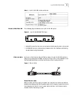
Connect Interface

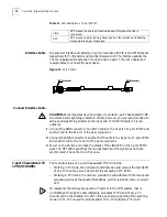
Optical Fiber

CAUTION:

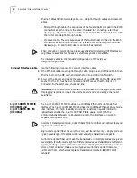
When connecting optical fiber, please note:

Do not bend optical fiber with excessive stress. The bend radius should be no 
less than 10 cm.

Ensure that the Tx terminal and the Rx terminal of the interface are connected 
correctly.

Keep the sectional surface of optical fiber clean and free from dust.

WARNING: 

Laser Danger! Do not observe the optical fiber connector connected 

with the laser in case the invisible laser radiation harms your eyes.

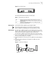
1

Find the Rx optical port and Tx optical ports on 100 FX MM/100 FX SM. Insert one 
end of an optical fiber into the Rx optical port of 100 FX MM/100 FX SM, and the 
other end into the Tx optical port of the peer device; insert one end of another 
optical fiber into the Tx optical port of 100 FX MM/100 FX SM, and the other end 
into the Rx optical port of the peer device.

2

Power on the Router and check the status of the LINK LED on the 
100BASE-MM/100BASE-F SM panel. ON means the Rx link has been connected 
and OFF means the Rx link is not connected. In the latter case, check the line.

4-port Enhanced Serial 
FIC (3C13863) 
8-port Enhanced Serial 
FIC (3C13864)

4-port / 8-port FIC stands for 4-/8-port enhanced high-speed sync/async serial 
interface card. The cards functions mainly to transmit, receive, and process the 
data on the synchronous/asynchronous serial interface. They support both 
synchronous and asynchronous modes. In the former case, they support the 
DTE/DCE mode.

Introduction to DTE and

DCE

A card is usually connected to an external modem for the dialing purpose. In this 
case, an appropriate baud rate must be set.

The synchronous serial interface can work in either DTE or DCE mode. Two devices 
directly connected should work as DTE and DCE respectively. The DCE device 
provides the synchronization clock and specifies communication rate, and the DTE 
device accepts the synchronization clock and communicates at the specified rate.

The Router normally works as a DTE. To know whether the specific equipment 
connected with the Router is DTE or DCE, please refer to the manual shipped with 
the equipment. 

Speed and transmission

distance of

synchronous/asynchron

ous serial interface

In different operating modes, the synchronous/asynchronous serial interface 
supports different electric signal specifications and baud rates. In addition, the 
maximum signal transmission distance not only depends on the specified baud 
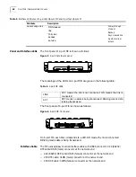
rate but also the selected cable. The following table shows how the cable type, 
baud rate, and the maximum signal transmission distance related to each other. 

Содержание 3C13840

Страница 1: ...http www 3com com Router 6000 Family Installation Guide Router 6040 3C13840 Router 6080 3C13880 Part No 10014361 Published June 2004 ...

Страница 2: ...t 3Com and a copy will be provided to you UNITED STATES GOVERNMENT LEGEND If you are a United States government agency then this documentation and the software described herein are provided to you subject to the following All technical data and computer software are commercial in nature and developed solely at private expense Software is delivered as Commercial Computer Software as defined in DFAR...

Страница 3: ...llation 23 Installing Modules 24 4 CONFIGURING THE ROUTER Establishing Configuration Environment 29 Router Configuration Fundamentals 34 5 SOFTWARE MAINTENANCE Software Maintenance Overview 37 Upgrading Program Files Using Xmodem Protocol 44 Upgrading Application Program via Ethernet Port 46 6 HARDWARE MAINTENANCE Hardware Maintenance 49 Power Module Removal and Installation 49 Fan Removal and Ins...

Страница 4: ...al E1 FIC 3C13823 65 4 port Channelized T1 PRI FIC 4T1 3C13870 and 4 port Fractional T1 FIC 4T1 F 3C13821 69 1 port Channelized E3 FIC 3C13888 71 1 port Channelized T3 1CT3 3C13889 72 1 port OC 3 ATM MM FIC 3C13882 1 port OC 3 ATM SM FIC 3C13884 1 port OC 3 ATM SML FIC 3C13886 74 2 port ADSL over POTS FIC 3C13872 76 A OBTAINING SUPPORT FOR YOUR PRODUCT Register Your Product to Gain Service Benefit...

Страница 5: ...ation http www 3com com Conventions Table 1 and Table 2 list conventions that are used throughout this guide Table 1 Notice Icons Table 2 Text Conventions Icon Notice Type Description Information note Information that describes important features or instructions Caution Information that alerts you to potential loss of data or potential damage to an application system or device Warning Information ...

Страница 6: ... your product If information in this guide differs from information in the release notes use the information in the Release Notes These documents are available in Adobe Acrobat Reader Portable Document Format PDF on the CD ROM that accompanies your router or on the 3Com World Wide Web site http www 3com com Words in italics Italics are used to Emphasize a point Denote a new term at the place where...

Страница 7: ... E1 FIC 3C13823 1 port OC 3 ATM MM FIC 3C13882 1 port OC 3 ATM SM FIC 3C13884 1 port OC 3 ATM SML FIC 3C13886 1 port Channelized E3 FIC 3C13888 1 port Channelized T3 FIC 3C13889 ATM and DSL Digital Subscriber Line DSL is a simple but highly efficient broadband technology that achieves great data transmission capacity over existing copper wiring by using the digital code modulation technology The A...

Страница 8: ... caused by malicious resources without compromising the normal network applications NAT of 6000 also provides the ALG Application Layer Gateway function to FTP and ICMP Support the authentication protocols such as PAP CHAP and data RADIUS Implement packet filter and stateful firewall for preventing the intrusion from an external networks Support VPN including GRE L2TP and MPLS and provide IPSec an...

Страница 9: ...ng slot 0 for the main control unit and slots 1 through 4 for FICs Two PSUs working in 1 1 backup mode can be installed in 6040 from the rear of the chassis The PSUs provide AC power The fan module is located at the left rear Both PSU and fan module are hot swappable 6040 Front Panel The following illustration details the components of the front panel of the 3Com Router 6040 Figure 1 Front Panel o...

Страница 10: ...2nd power supply 6080 Components The 6080 has nine slots on the front panel using slot 0 for the main control unit and slots 1 through 8 for FICs Two PSUs working in 1 1 backup mode can be installed in the 6080 from the rear of the chassis The PSUs provide AC power and you may make selection as needed The fan module is located at the left rear Both PSU and fan module are hot swappable 6080 Front P...

Страница 11: ...6 9 FIC Slot7 10 FIC Slot8 11 ESD preventive wrist strap port 6080 Rear Panel The following illustration details the components of the rear panel of the 3Com Router 6080 Figure 3 Rear Panel of the 3Com Router 6080 1 Fan module 2 Grounding screw 3 ESD preventive wrist strap port 4 PWR1 first power supply 5 PWR2 second power supply 1 2 3 4 5 ...

Страница 12: ...ot program file Table 3 System Description of 6040 and 6080 Item 6040 6080 FIC slot 4 8 Fixed interface 2 10 100Mbps Ethernet ports 1 AUX port 1 console port 2 10 100Mbps Ethernet ports 1 AUX port 1 console port Processor 733MHz 733MHz Boot ROM 1024KB 1024KB SDRAM 256MB 256MB NVRAM 512KB 512KB Flash 32MB 32MB Dimensions W x D x H 436 2 mm x 420 mm x 130 5 mm 436 2 mm x 420 mm x 219 5 mm Weight 17 ...

Страница 13: ...to process protocols forward low speed packets control interfaces and detect faults The state monitoring information such as the operation states of FAN PWR and system can be shown directly via the LEDs on the RPU or reported to the network management system In addition RPU also provides the hardware reset button RESET Figure 4 RPU Figure 5 LEDs and buttons ...

Страница 14: ... means CPU has received an alarm signal for PWR or FAN due to overheating for example FAN FAN failure LED ON means the FAN is no in place or its rotation is obstructed PWR1 PWR1 failure LED ON means PWR1 has failed PWR2 PWR2 failure LED ON means PWR2 has failed RESET RPU hardware reset button 10 100BA SE TX LED LINK green OFF means the link is not connected and ON means the link is connected ACT y...

Страница 15: ... the system Power Modules controls functions of overcurrent protection and overvoltage protection You can connect the PWR to the backplane by inserting it from the rear of router chassis It is hot swappable and its switchover will not affect the ongoing system operation If you want to install a 6000 Router in a communication equipment room you should make sure that the power distribution cabinet c...

Страница 16: ...16 CHAPTER 2 INTRODUCING THE ROUTER 6000 FAMILY Figure 6 AC Power LEDs Figure 7 Front Panel of AC Power Module ...

Страница 17: ... and is in the range of 50 to 100 The FAN controller uses two parameters i e low temperature threshold and high temperature threshold to control the rotation speed of the fans with the former corresponding to 100 rotating speed and the latter corresponding to 50 rotating speed The system will send out rotation stop alarm signals in case any fan fails The alarm and state LEDs of FAN are located on ...

Страница 18: ...18 CHAPTER 2 INTRODUCING THE ROUTER 6000 FAMILY ...

Страница 19: ...ere are no protective boards in front or at the back of the router rack Cleanliness Requirements Dust is harmful to the safe operation of the Router Dust on the chassis may result in static absorption and causes poor contact of the metal connection components or points There should not be explosive conductive magnetic and corrosive dust in the equipment room where 3Com 6000 Routers are located and...

Страница 20: ...observing or moving it so as to avoid direct contact with the elements on it Electromagnetic Environment Requirements All interference sources will affect the Router negatively in the conduction patterns of capacitance coupling inductance coupling electromagnetic wave radiation and common impedance including grounding system coupling To prevent the interference Take effective measures against elec...

Страница 21: ...e sure that the workbench is well grounded Safety Recommendations When installing or working on a Router you should Keep the Router far away from heat sources and water liquid Make sure that the Router has been correctly grounded Wear ESD preventive wrist strap during installation and maintenance Connect the cables to the ports appropriate to them Above all do not insert the telephone cable includ...

Страница 22: ...r other DCE equipment Console terminal it could be a common PC Equipment related to the selected FICs 8 Technology documentation 1 SET Include printed documentation Installation Manual for the Router and CD ROM documentation 9 Installation mechanical part 1 SET 11 External cable suite 1 SET Optional cables including Ethernet cable AUX cable synchronous asynchronous serial cable E1 cable optical ca...

Страница 23: ...ensions Take the following steps to mount a Router 1 Ensure the rack is stable 2 Fix the mounting brackets attached with a fixed cabling rack onto both sides of the chassis with a Phillips screwdriver Skip this step if you do not fix the router on the rack 3 Install the Router on the shelf guides and push it into the rack Since 6080 Router is rather heavy it needs two people to carry from both sid...

Страница 24: ...f RPU PWR and various FICs Connect the Ground PGND WARNING The normal connection of PGND wire for the Router is the essential safeguard against the lightning shocks and interference Therefore you must first correctly connect the PGND wire when installing and using the Router 6000 Routers provide a separate PGND screw You must securely connect the PGND to the ground ensuring the leakage power to be...

Страница 25: ... The power socket of an AC input Router Recommended AC power socket Use a 3 line single phase power socket with a grounding terminal which should be reliably connected to the ground in the building Make sure that the power supply for the building has been well grounded before connecting the AC power cord Connect AC Power Cord 1 Check that the PGND wire has been correctly connected to the ground 2 ...

Страница 26: ...console cable Before you can configure the Router at the console terminal connect the console cable in the following steps 1 Select a console terminal Console terminal can be a standard ASCII terminal possessing an RS232 serial port or a regular PC but the latter is often used 2 Connect the cable Power off the Router and console terminal and connect the RS232 serial port to the console port on the...

Страница 27: ...port on the RPU for example 1 Use a crossover cable to connect the Router to a PC or another Router by connecting one end of the cable to the Ethernet port on the Router and the other end to the PC or the peer router Use a straight through cable to connect the Router to a HUB or LAN Switch by connecting one end of the cable to the Ethernet port on the Router and the other end to the HUB or the LAN...

Страница 28: ... the remote equipment Verify Installation During router installation you must verify the installation each time you power on the Router making sure that Enough clearance has reserved around the Router for adequate dissipation and the cabinet is stable enough The correct power supply is used The connection of the PGND wire of the Router is correct and secure The connections with other devices such ...

Страница 29: ... and DB25 connector or DB9 connector to the serial interface of a PC as shown below Figure 1 Local configuration through CON port Setting the parameters of configuration terminal To set the configuration parameters follow below 1 Start the configuration terminal and set up a new connection If the configuration is performed through a PC the terminal emulation program HyperTerminal of Windows95 98 N...

Страница 30: ... are set as follows a Select a connection port While implementing the local configuration select the serial interface to be connected in the Connect Using box as shown below Please notice that the selected serial interface should be consistent with the actual serial interface connected by the console cable ...

Страница 31: ...lows Baud rate 9600 Data bits 8 Parity check None Stop bits 1 and Flow control None Click the OK button to return to the HyperTerminal interface 5 Set HyperTerminal properties Select Property Settings on the HyperTerminal and enter the property setting window shown below Select VT100 or auto detection as terminal simulation type press Ok and return to the HyperTerminal window ...

Страница 32: ...witch in the equipment room so that in case of an electrical accident power can be turned off 1 Power up the Router Confirm the following while the router is booting Whether the LEDs on the front panel are normal Whether the configuration terminal display is normal For the local configuration the booting interface displays on the configuration terminal after the Router is powered on 2 Upon complet...

Страница 33: ...g and executing If you do not press Ctrl B the system will take the next step The system provides Boot ROM master system automatic updating function Before executing an application if it finds the Boot ROM master system version is different from that recorded in the Boot ROM chip it will automatically update the Boot ROM master system and reset it The following information will display Update Boot...

Страница 34: ... and reliability 2 Based on the above requirements draw a clear and detail networking diagram 3 Configure the WAN interface of the Router First configure the physical operating parameters such as synchronous asynchronous serial interface baud rate and synchronous clock of the interface according to the transmission medium of the WAN For the dial up interface you need to configure DCC parameters fo...

Страница 35: ... www 3com com 3nd Command Line Interface The command line interfaces provided by 3Com 6000 Series Routers include a series of configuration commands through which a user can configure and manage the router The command line interface has the following features Performs the local configuration through CON port Performs the local or remote configuration through the Telnet command which can be used to...

Страница 36: ...l port and Asynchronous port The interfaces are configured in the order of sequence number Figure 2 Example 6080 Router slot arrangement Interface numbering rule 6000 interfaces are numbered in three dimensions The rules are as follows The interfaces are numbered in the interface type X Y Z format in which interface specifies the interface type as serial asynchronous ethernet or ATM etc X specifie...

Страница 37: ...Boot sub menu can upgrade and start program While Boot main menu upgrades and starts application program Build up a configuration environment and then boot the Router 1 Enter N and the following information will be displayed on the terminal screen Press CTRL A to Stop AutoBoot Starting 2 Press Ctrl A in five seconds after Starting pops up then the system enters Boot sub menu In order to access the...

Страница 38: ...s Enter When you select 5 the system prompts Enter your choice 1 5 5 Change The BaudRate On PC Side First 3 Select File Attributes at HyperTerminal in the configuration PC and press Configuration in the dialog box In the dialog box change the baudrate to a desired value and press OK 4 Disconnect the system and resume dialup to make the new parameter take effect The Current BaudRate is 115200 You s...

Страница 39: ...t SubMenu 5 Modify Bootrom Password 6 Reboot Enter your choice 1 7 _ If you use Flash for the first time and reading or writing Flash is required Flash will be formatted first Then the following information will be prompted Formatting Flash please waiting several minutes done Starting host program in default mode Enter 1 in Boot main menu and the system will first read Flash description area to ge...

Страница 40: ...loading details 2 Downloading to Flash Enter 2 in serial port sub menu and the system will download the main boot file to Flash via serial port using Xmodem protocol 3 Modifying serial port parameters Enter 3 in serial port sub menu to modify baudrate of the serial port on RPU card The following information is displayed BAUDRATE SET Note Change The HyperTerminal s Baudrate Accordingly BaudrateAval...

Страница 41: ... file from the host to Flash 3 Downloading the backup boot file to Flash via Ethernet port Enter 3 in Ethernet port sub menu and the system will download the backup boot file from the host to Flash via Ethernet port 4 Downloading the secure boot file to Flash via Ethernet port Enter 4 in Ethernet port sub menu and the system will download the secure boot file from the host to Flash via Ethernet po...

Страница 42: ...cally Then the system enters boot file control menu BOOT FILE CONTROL 1 Show Available Boot File 2 Set Main Boot File 3 Set Backup Boot File 4 Exit To Main Menu Enter your choice 1 4 Displaying available boot files in the Flash Enter 1 in Boot file control sub menu The system lists all available boot files in the Flash as follows Available boot file s M MAIN B BACKUP S SECURE No Type Date Time Siz...

Страница 43: ...le main bin to N A Setting the backup boot file In Boot file control sub menu input 3 to set the backup boot file The following information appears Input backup boot file name router bin Input the backup boot file name behind the right arrow indicator The choose 1 to see if it has taken effect Available boot file s M MAIN B BACKUP S SECURE No Type Date Time Size Name 1 M Apr 12 2003 00 38 29 55340...

Страница 44: ... Xmodem Protocol Upgrading Boot ROM Program Detailed procedures 1 Step 1 Connect the configuration PC as per Figure 4 1 2 Step 2 Start the router and press Ctrl A in five seconds when the system prompts Starting to enter Boot sub menu 3 Step 3 Change the baudrate of the serial port on RPU card to increase loading rate See Modifying serial port parametersModifying serial port parameters for more de...

Страница 45: ...PC is not ready yet press Ctrl X to exit from loading program files Figure 1 Setting Parameters 6 The system prompts the following information after you press Send Figure 2 Xmodem File When the loading is completed the system prompts XMODEM downloading CC download successfully Update Bootrom done Excluding the time to download program files it takes 10 seconds to upgrade Boot ROM program ...

Страница 46: ...les and Xmodem protocol in Transfer Send files in HyperTerminal 7 Send files 8 If you have selected downloading application files to Flash you need to return to Boot main menu after the system writes application files into Flash and select 2 to start the router from Flash Upgrading Application Program via Ethernet Port Through Ethernet port you can upgrade application program at high rate using FT...

Страница 47: ... The IP address of TFTP Server flags f Enter 0x80 for TFTP mode For FTP upgrade mode you should set the following parameters file name The file name to be downloaded inet on ethernet e The IP address for the downloading port in the router which is user defined and should not be in conflict with other device addresses in the network host inet h The IP address of FTP Server user u username which sho...

Страница 48: ...48 CHAPTER 5 SOFTWARE MAINTENANCE ...

Страница 49: ...Remove a Power Module 1 Turn off power switch 2 Remove the power cord connected to the power module to be removed and loosen the two captive screws in the top panel of the module 3 Hold the handle of the module and gently pull the module out along the guides Figure 1 Power Module Removal Install a Power Module 1 Hold the handle of the power module panel slowly push the module into the chassis alon...

Страница 50: ...n is rather long and therefore use one hand to hold the bottom of the fan while the other hand holds the handle attached to the front of the fan and pull it out slowly Be careful and do not put your finger into the rotating fan Figure 2 Fan Removal Install a Fan 1 Hold the handle attached to the front of the fan with one hand and hold the bottom with the other hand Slowly insert the fan into the c...

Страница 51: ...e router If there are two power modules installed turn both of them off 2 Align the corners of the far edge with the guides in RPU slot and push the RPU inside the router At the same time push the handles at both side of the RPU inward until it well touches the RPU panel 3 Fasten the captive screws and fix the RPU on the router 4 Turn ON power 5 Check if the fan status indicator on the RPU is norm...

Страница 52: ...52 CHAPTER 6 HARDWARE MAINTENANCE ...

Страница 53: ...em has some fault the terminal may display nothing or only illegible characters Fault nothing being displayed on the terminal After the Power On Self Test POST of the Router the terminal does not display any information Please check If the power system is normal If the console cable is connected correctly If there s nothing wrong after all the items above have been checked it is likely that there ...

Страница 54: ...change ErrDev to wancom which is the application upgrade device of 6000 Router Fault 2 Start the Router upgrade the application software with the TFTP approach and the following information is displayed DownLoad Program To Flash Through Net Port boot device wancom unit number 0 processor number 0 file name 6000 bin inet on ethernet e 1 1 1 1 host inet h 1 1 1 2 user u user ftp password pw password...

Страница 55: ...ir doesn t link correctly Loading Failed Troubleshooting The problem occurs because the IP address of the computer is not correctly configured To solve the problem make a correct configuration of the IP address Fault 4 Start the Router upgrade the software with the TFTP approach and the system displays the following prompt DownLoad Program To Flash Through Net Port boot device wancom unit number 0...

Страница 56: ...56 CHAPTER 7 TROUBLESHOOTING ...

Страница 57: ...of a FIC CAUTION The shielding fingers on the front panel of FIC achieve special electromagnetic shielding effect for the whole Router Please ensure their integrity when uninstalling or replacing an FIC and never damage them If you do not want to install a new FIC after removing the old one install a blank filter panel to keep off the dust and ensure the adequate ventilation of the Router 3Com 600...

Страница 58: ...atus reporting Generally you can locate the problem by performing the following operations if an FIC is not working normally Check the interface cables making sure that you have used the correct cables View the LEDs on the FIC panel ensuring that the FIC is working normally Executing the configured display command ensuring that the interface has accepted the configuration and is working normally I...

Страница 59: ... pair with RJ45 connectors Pins 1 and 2 of the interface are at the transmitting terminal and Pins 3 and 6 are at the receiving terminal Figure 2 Ethernet Cable Make Ethernet cable Ethernet cable uses the category 5 twisted pair composed of eight cores that are identified and grouped by their insulation layer colors Usually a unicolor wire and the white unicolor wire for it are in pairs But someti...

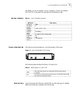
Страница 60: ...been connected and OFF means that the link is not connected In the latter case check the line CAUTION You must connect a cable to the interface with the appropriate mark Misplugging is prone to impair the interface card and even damage the router mainframe 1 port 100 FX MM FIC 3C13860 and 1 port 100 FX SM FIC 3C13862 The 1 port 100FX MM FIC provides one 100Mbps Ethernet multi mode fiber interface ...

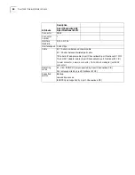
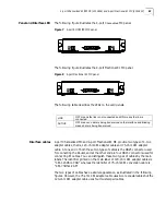
Страница 61: ... fiber The optical interfaces of both cards are SC optical receptacles so the optical fibers with SC connector should be selected Figure 4 SC optical fiber connector Attribute Description 100 FX SM 100 FX MM Connector SC Connector number 1 Optical fiber mode Single mode Multimode Max transmission distance 15km 2km Central wavelength 1310nm 1261 1360nm 1315nm 1270 1360nm Transmitting optical power ...

Страница 62: ...nds for 4 8 port enhanced high speed sync async serial interface card The cards functions mainly to transmit receive and process the data on the synchronous asynchronous serial interface They support both synchronous and asynchronous modes In the former case they support the DTE DCE mode Introduction to DTE and DCE A card is usually connected to an external modem for the dialing purpose In this ca...

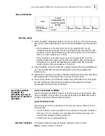
Страница 63: ...ate bps Max transmission distance m 2400 60 2400 1250 4800 60 4800 625 9600 30 9600 312 19200 30 19200 156 38400 20 38400 78 64000 20 56000 60 115200 10 64000 50 2048000 30 Table 5 Interface attributes of 4 port Sync Async FIC and 8 port Sync Async FI Attribute Description Synchronous Asychronous Connector DB 28 Number of Connectors 4 4 port FIC 8 8 port FIC Interface standard and operating mode V...

Страница 64: ... sync async serial interface cable with DB28 connector V 24 RS232 DTE cable DB25 male connector at the network end V 24 RS232 DCE cable DB25 female connector at the network end V 35 DTE cable 34PIN male connector at the network end V 35 DCE cable 34PIN female connector at the network end Services Supported DDN leased line Terminal access service Dialup through Modem Backup Async leased line Dumb t...

Страница 65: ... the CSU DSU If the WAN is a dialup line please connect the cable to the serial interface of the analog Modem 4 Power on the router and check the status of the LINK LED of the FIC It is off when the line is faulty and signal is out of step 4 port Channelized E1 PRI FIC 3C13866 and 4 port Fractional E1 FIC 3C13823 4 port Channelized FIC 4 port Channelized FIC function to transmit receive and proces...

Страница 66: ...alanced twisted pair cable 120 ohm 4E1 adapter cable 4 port Channelized 4 port Fractional E1 FIC 75 ohm 4E1 adapter cable 4 port Channelized 4 port Fractional E1 FIC Coaxial connector network connector 75 to 120 ohm adapter with BNC connector Operating mode E1 CE1 ISDN PRI only supported by 4 port Channelized FIC FE1 only supported by 4 port Fractional E1 FIC Supported service Backup Leased line a...

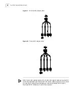
Страница 67: ...wo types of cables is the DB25 connector used for connecting the Router and at the other end are four DB15 connectors used for connecting E1 cables You can distinguish these two types of cables by the main labels The identifier printed on the main label of 120 ohm 4E1 adapter cables is 4E1 120Ohm CAB whereas the identifier of 75 ohm 4E1 conversion cable is 4E1 75Ohm CAB The two types of cables hav...

Страница 68: ...dapter cable Both 75 ohm 4E1 adapter cable and 120 ohm 4E1 adapter cable are required for 4 port Channelized 4 port Fractional E1 FIC but E1 cable is optional so you need to order the E1 cable when purchasing an 4 port Channelized FIC or 4 port Fractional E1 FIC Otherwise it will not be provided ...

Страница 69: ...t the other end of the 4E1 adapter cable and connect the connector to the E1 cable 4 Power on the Router and check the status of the LINK LED on the card panel An OFF LED means that the line has failed and the signal has not been synchronized Check the line in this case 4 port Channelized T1 PRI FIC 4T1 3C13870 and 4 port Fractional T1 FIC 4T1 F 3C13821 4 port Channelized T1 PRI FIC 4 port Channel...

Страница 70: ...ute Description Connector RJ48 Connector number 4 4 port T1 C1 PRI FIC 4 port Fractional T1 FIC Interface standard G 703 T1 102 G 704 Interface speed 1 544Mbps Cable T1 cable 100 ohm standard shielded cable Operating mode CT1 ISDN PRI 4 port Channelized T1 PRI FIC FT1 4 port Fractional T1 FIC Supported service Backup Leased line access ISDN PRI 4 port T1 C1 PRI FIC LINK OFF means the link is not c...

Страница 71: ... an E3 channel can be channelized into 16 E1 lines each supporting both the operating modes of E1 and CE1 E23 is used to indicate either E2 to E3 multiplex or E3 to E2 demultiplex and E12 to indicate E1 to E2 multiplex or E2 to E1 demultiplex E23 and E12 discussed here represent the demultiplex process Interface Attributes Table 10 1 port Channelized E3 FIC interface attributes Panel and Interface...

Страница 72: ... 3 Power on the Router and check the status of the LINK LED on the 1 port E3 FIC panel An OFF LED means that the line has failed and the signal has not been synchronized Check the line in this case 1 port Channelized T3 1CT3 3C13889 The main functions of 1 port Channelized T3 FIC include Working in T3 mode the card can transmit receive and process the fast traffic of one T3 channel as well as prov...

Страница 73: ...s the LEDs on the card panel Table 13 LED description of 1 port T3 FIC Interface Cable 1 port Channelized T3 FIC and 1 port E3 FIC use the same type of interface cables and make the connection in the same way Attribute Description Connector SMB Connector number 2 Interface standard G 703 G 704 G 752 Interface speed 44 736Mbps Cable T3 cable 75 ohm coaxial cable Operating mode T3 CT3 Supported serv...

Страница 74: ...e ATM cards Panel and Interface LED The following figure illustrates the 1 port OC 3 ATM MM panel Figure 16 1 port OC 3 ATM MM panel Attribute 1 port OC 3 ATM MM 1 port OC 3 ATM SM 1 port OC 3 ATM SML Optical fiber connector SC Connector number 1 Interface standard SONET OC 3 SDH STM 1 Interface speed 155Mbps Cable and the max transmission distance Multi mode optical fiber of 2km transmission dist...

Страница 75: ...nectors the connectors of the optical fibers must also be SC connectors The external optical cable suite provides the users with optical cables of variable lengths For the connector appearance optical cable connection and the safety precautions refer to the section 8 5 5 Connect Interface Optical Fiber CAUTION Laser Danger Do not stare at the optical fiber connector connected with the laser in cas...

Страница 76: ...nlink rate and a speed in the range of 32 Kbps to 1 Mbps uplink rate ADSL interface cards Supportfor ADSL over POTS Annex A Allow manual activation deactivation of ADSL line and support SAR loopback which facilitates fault isolation Support interface standards of G DMT G Lite and T1 413 and the configuration of auto sensing Support network lattice coding except for G Lite on ADSL interfaces enhanc...

Страница 77: ...ate mode a splitter is required Follow these steps to connect the cables 1 Plug one end of a telephone cable into the ADSL port on the Router and the other end into the inbound ADSL port on the splitter 2 Connect the telephone to the phone port on the splitter with another telephone cable 3 Connect the outbound ADSL port on the splitter to the PSTN with a third telephone cable Figure 21 Connect 2 ...

Страница 78: ...78 CHAPTER 8 FLEXIBLE INTERFACE CARDS ...

Страница 79: ... 3Com Extended Warranty and Professional Services is available at http www 3com com Contact your authorized 3Com reseller or 3Com for additional product and support information Troubleshoot Online You will find support tools posted on the 3Com web site at http www 3com com 3Com Knowledgebase helps you troubleshoot 3Com products This query based interactive tool is located at http knowledgebase 3co...

Страница 80: ...u must first obtain a return authorization number RMA Products sent to 3Com without authorization numbers clearly marked on the outside of the package will be returned to the sender unopened at the sender s expense If your product is registered and under warranty you can obtain an RMA number online at http eSupport 3com com First time users will need to apply for a user name and password Telephone...

Страница 81: ... 988 2112 0 810 444 3COM 1 800 998 2112 1 800 998 2112 1 800 998 2112 52 5 201 0010 1 800 998 2112 1 800 998 2112 0800 13 3COM 1 800 998 2112 AT T 800 998 2112 AT T 800 998 2112 AT T 800 998 2112 1 800 998 2112 AT T 800 998 2112 AT T 800 998 2112 Guatemala Haiti Honduras Jamaica Martinique Mexico Nicaragua Panama Paraguay Peru Puerto Rico Salvador Trinidad and Tobago Uruguay Venezuela Virgin Islan...

Страница 82: ...82 APPENDIX A OBTAINING SUPPORT FOR YOUR PRODUCT ...

Отзывы: