


2N
- ISDN BRI GSM Enterprise Gateway
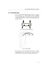
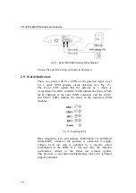
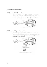
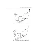
Fig. 14 - Basic ISDN GSM Gateway Wiring Diagram
Choose the specific wiring as shown in Section 4.
2.9.
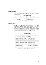
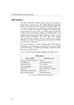
Status Indicators
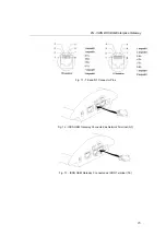
There is a panel with five LEDs on the gateway upper cover
for a quick GSM gateway status detection (see Fig. 15).
The
Power
LED signals that the gateway as a whole is
in operation. The
BRI 1
and
BRI 2
LEDs indicate the status of both
the B channels of the basic ISDN extension, and the
GSM 1
and
GSM 2
LEDs indicate the status of the respective GSM
modules.
Fig. 15 - Signalling LEDs
Basic diagnostic tests and gateway initialisation are performed
automatically whenever the gateway is connected to supply
voltage. Each test step is signalled by a specific colour
combination of the LEDs. If a test step fails, the indicator
combination related to the failed test remains lighted.
This provides a convenient troubleshooting tool to the technical
support personnel.
16
Содержание ISDN BRI GSM
Страница 1: ...2N ISDN BRI GSM Enterprise Gateway User Manual Version 1 1 ...
Страница 4: ......
Страница 8: ......
Страница 46: ...2N ISDN BRI GSM Enterprise Gateway Fig 28 Incoming Call Processing Procedure 36 ...
Страница 88: ...2N ISDN BRI GSM Enterprise Gateway 78 ...
Страница 106: ...2N ISDN BRI GSM Enterprise Gateway 96 ...
Страница 109: ...2N ISDN BRI GSM Enterprise Gateway 2005 2N TELEKOMUNIKACE a s Praha PB 1272 v 1 1 99 ...


