2 EASY
ELECTRIC LOCK CONNECTION
SPECIFICATION
S
1) Door Lock Controlled with Internal Power
1. The door lock is limited to 12Vdc, and holding current must be less
than 250mA when using internal power supply mode
2. The Unlock Mode Parameter must be set to 0
(
default).
3. Jumper set to 1-2 position for power-off-to-unlock safety
type(
Normally closed mode
); set to 2-3 position for power-on-to
-unlock type(
Normally open mode
).
4. If different unlocking time is needed to be configured, change the
unlock time on door station,detail
ed
information refer to DT system
technical guide
2) Door Lock Controlled with External Power
1. The external power supply must be used according to the lock
2. The jumper must be taken off before connecting
3. Setup the
Unlock Mode Parameter
for different lock types
•
Power-on-to-
U
nlock type:Unlock Mode=0(default)
•
Power-off-to-
U
nlock type:Unlock Mode=1
4. If different unlocking time is needed to be configured, change the
unlock time on door station,more detail information refer to DT system
technical guide
JP_LK
12V 300mA
Exit button
Jumper position in 2-3
+
-
+12V
LK -
LK+
N.O.
EB-
EB+
1 2 3
Power-on-to-Unlock type:
Power-on-to-Unlock type:
12V 300mA
Jumper position in 1-2
+12V
LK -
LK+
N.O.
EB-
EB+
+
-
JP_LK
1 2 3
Exit button
Power-off-to-Unlock type:
Power-off-to-Unlock type:
+
+
-
-
+12V
LK - (GND)
LK+(COM)
N.O.
EB-
EB+
Take off the Jumper
JP_LK
Cut off the line
1 2 3
Exit button
+12V
LK - (GND)
LK+(COM)
N.O.
EB-
EB+
Take off the Jumper
+
+
-
-
JP_LK
Cut off the line
1 2 3
Exit button
•
Power:
26Vdc(supplied by PC6)
•
Power Consumption:
1W standby, 5W working
•
Unlock Power output:
12Vdc,250mA
•
Unlock tim
e
:
1~99s
•
Working temperature:
- 20ºC ~ +55ºC
•
Dimension
s
:
316(H)x133(W)x48(D)mm
INSTALLATION GUIDE
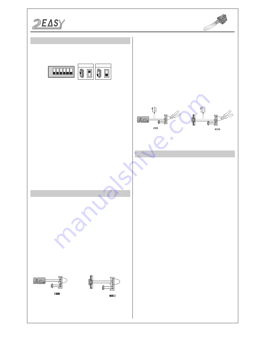
DIP SWITCHES SETTING
Totally 6 bits can be configured by dip-switch. The switches can be
modified either before or after installation, but restarting the power is
needed whenever the switches have been modified
Bit-1 and Bit 2 is for door station ID settings. When multi door stations
are installed in the system, these two bit must be set correctly, the
first door station set to 00, the second one set to 01, the third one set
to 10, the fourth one set to 11. If only one door station is installed, set
to 00.
Bit-3 is for single or double row button door station selection. If the
door station is a double row button, such as DMR21-D8, set this bit to
0. For single row button door station,set to 1.
Bit-4 is for button code selection. if use the default codes for each
button of the door station, set to 0. If use the programmed codes, set
to 1.(the code for each button can be programmed by software, detail
information refer to DT system technical guide)
Bit-5 is for unlocking time quick setting. 0 is the default setting,and the
default time is 1 second. If set to 1,the unlock time is 5 seconds(the
unlock time can be modified by door station or software)
Bit-6 is for activating the key A and key B. Normally key A and key B
is not activated(about the functions of key A and key B,please refer to
DT system technical guide ),Just when it set to 1,the key A and key B
is activated.
ON(1)
=
OFF(0)
=
ON
ON
ON
1 2 3 4 5 6
DMR21 Technical M
a
nu
al
-4-


