Zimmer HRC-03-080663, Installation And Operating Instructions Manual
The Zimmer HRC-03-080663 is an innovative device designed for diverse applications. For a hassle-free installation and smooth operation, make sure to access the detailed "Installation And Operating Instructions Manual". Download it for free from our website, ensuring a successful setup and optimal performance.
Share
Download


Reviews:
No comments
Related manuals for HRC-03-080663

PiSloth
Brand: SunFounder Pages: 105

KoiBot
Brand: QNAP Pages: 44

Jet Bot VR30T80 Series
Brand: Samsung Pages: 240

Wacky Robot
Brand: 4M Pages: 2

Octopus Robotic Claw
Brand: 4M Pages: 2

COMPACT
Brand: EasyRobotics Pages: 38

TUMBLING HEDGEHOG
Brand: Thames & Kosmos Pages: 44

Baby
Brand: Gnom Pages: 30

TIGER ELECTRONICS Robo-Chi Pets Series
Brand: Hasbro Pages: 2

Girl Powered VEX IQ Speed Build
Brand: Vex Robotics Pages: 8

ROTOR HDA
Brand: Singer Instruments Pages: 30

mGrip P4Y
Brand: SOFT ROBOTICS Pages: 6

RSH1C
Brand: MISUMI Pages: 88

MaeGo
Brand: DIDIJIN Pages: 21
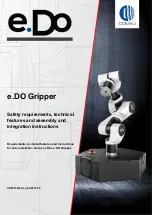
e.DO
Brand: Comau Pages: 28

C5G-R1C
Brand: Comau Pages: 82

steeper
Brand: be bionic Pages: 40

YouRing
Brand: Alumotion Pages: 16


