background image

1

© KEMET Electronics Corporation • KEMET Tower • One East Broward Boulevard 

R7001_EA2_EB2 • 5/19/2021

Fort Lauderdale, FL 33301 USA • 954-766-2800 • www.kemet.com

Built Into Tomorrow

Benefits

•  Low power consumption (< 200 mW)

•  Compact and lightweight

•  Low magnetic interference

•  Breakdown voltage: 1,000 VAC (1,500 VAC surge),  

FCC Part 68 compliant

•  Tube or embossed tape and reel packaging

•  UL recognized (E73266) and CSA certified (LR46266)

•  Surface mount and through-hole options

Overview

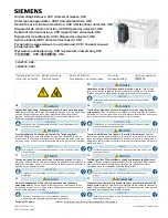
The KEMET EA2/EB2 miniature signal relays offer a 

compact case size in a flat package. Minimal board space 

is consumed with either a through-hole or surface mount 

configuration. These relays are recognized by UL and CSA, 

while also being compliant with Part 68 of the FCC’s 1,500 

V surge capacity.

Applications

•  Electronic switching systems

• PBX

•  Terminal equipment

•  Telephone systems

Miniature Signal Relays

EA2/EB2

Part Number System

EB2-

3

S

NU

-L

Series

Coil Voltage

Latch Type

Lead Type

Packaging

EA2- = Through-hole mount 

EB2- = Surface mount

3 = 3 VDC

4.5 = 4.5 VDC

5 = 5 VDC

12 = 12 VDC

24 = 24 VDC

Blank = Non-latch type

S = Single coil latch type

T = Double coil latch type

NU = Standard

NJ = Trimmed

Blank = Tube

-L = Embossed tape on reel

Summary of Contents for KEMET EA2 NU Series

Page 1: ...ignal relays offer a compact case size in a flat package Minimal board space is consumed with either a through hole or surface mount configuration These relays are recognized by UL and CSA while also...

Page 2: ...niature Signal Relays EA2 EB2 Dimensions Millimeters EA2 Series D Maximum B Maximum 0 33 0 25 0 5 H Maximum P1 P2 K General tolerance 0 2 EB2 Series B Maximum D Maximum H Maximum K P1 P2 11 5 0 25 0 5...

Page 3: ...d UL508 1 E73266 30 VDC 1 A resistive 110 VDC 0 3 A resistive 125 VAC 0 5 A resistive CSA CSA Certified CSA 22 2 14 LR46266 1 Spacing UL114 UL478 Environmental Compliance All KEMET relays are RoHS Com...

Page 4: ...2 3 1 NU 3 0 Surface Mount Tube EB2 4 5 1 NU 4 5 Surface Mount Tube EB2 5 1 NU 5 0 Surface Mount Tube EB2 12 1 NU 12 0 Surface Mount Tube EB2 24 1 NU 24 0 Surface Mount Tube EB2 3 1 NU L 3 0 Surface M...

Page 5: ...onds maximum Note KEMET recommends cooling down a printed circuit board to less than 110 C within 40 seconds after soldering Manual Soldering Solder temperature 350 C maximum Solder time 3 seconds max...

Page 6: ...VA Maximum Switching Voltage 220 VDC 250 VAC Maximum Switching Current 1 A Maximum Carrying Current 2 A Minimum Contact Ratings 10 mVDC 10 A 1 Initial Contact Resistance 75 m maximum initial Operating...

Page 7: ...type relays should be initialized to a known position before using Only the specified polarity should be used to energize the coil Double Coil Latch Type at 20 C 2 3 Nominal Coil Voltage VDC Coil Res...

Page 8: ...Type Rating Ambient Temperature Non latch Voltage 5 of nominal voltage 40 to 85 C Single Coil Double Coil Square pulse rise and fall time is rapid Pulse height 5 of nominal voltage Pulse Width 10 ms...

Page 9: ...IN for maximum values under continuous use MAXIMUM COIL VOLTAGE This is a maximum value of permissible alteration Inquire with NEC TOKIN under continuous use DC Resistive AC Resistive 250VAC 220VDC Co...

Page 10: ...AMBIENT TEMPERATURE This shows a typical change of operate release voltage The value of must operate is estimated so coil voltage must be applied more than this value for safety operation For hot star...

Page 11: ...etailed product data prior to the purchase EA2 EB2 SERIES 10 100 50 0 0 5 1 0 1 5 2 0 Breakdown voltage K V 100 50 0 1 0 1 5 2 0 2 5 100 50 0 0 5 1 5 2 0 2 5 BREAKDOWN VOLTAGE Sample EA2 5NU 10peices...

Page 12: ...0 1 75 12 1 0 4 max 8 1 14 7 24 0 4 1 5 2 2 16 11 5 2 0 1 75 12 1 0 4 Maximum 8 1 14 7 Direction mark Sprocket hole Direction of unreeling Direction mark Sprocket hole Direction of unreeling 750 piec...

Page 13: ...nder the actual operating conditions Evaluate the performance by using the actual circuit before using the relay 2 Driving relays If the internal connection diagram of a relay shows and symbols on the...

Page 14: ...isted in the printed version catalog 2007 08 03 P0886EMDD03VOL01E 13 ctual operating conditions ng the actual circuit before am of a relay shows and rated voltage to the relay in pled DC current sourc...

Page 15: ...ight shock has been applied to the relay thoroughly evaluate its operation before using it Latching relays are factory set to reset state for shipment A latching relay may be set however by vibration...

Page 16: ...e the correct products for their application Any technical advice inferred from this Information or otherwise provided by KEMET with reference to the use of KEMET s products is given gratis and KEMET...

Reviews: