wireless Seismic RT System 2, Deployment Manual
The Wireless Seismic RT System 2 is a cutting-edge technology that revolutionizes seismic data acquisition. Achieve seamless field operations with our comprehensive Deployment Manual, now available for free download on our website. Maximize your productivity and efficiency with step-by-step instructions and guidelines. Visit manualshive.com to access your manual today.
Share
Download


Reviews:
No comments
Related manuals for RT System 2

CR300 series
Brand: Campbell Pages: 86

Pendant Event
Brand: Hobo Pages: 4

OM8800D
Brand: Omega Pages: 45

HOBO MX2300 Series
Brand: HH Solutions Pages: 9

AXN
Brand: Curtiss-Wright Pages: 74

LOG200 Series
Brand: Dostmann Electronic Pages: 17

GLOG V2
Brand: Geomatics Pages: 16

Intermec CN3eG
Brand: DPAS Pages: 25

Contoil DFM 8EDM
Brand: aqua metro Pages: 20

ADwin-Gold II
Brand: Jäger Pages: 224

Mon-T2
Brand: Tamprecords Pages: 6

iDash 1.8
Brand: banks Pages: 16

MT643
Brand: Major tech Pages: 12

Ebro EBI 16
Brand: Xylem Pages: 40

OM-USB-5201
Brand: Omega Pages: 28

A21001
Brand: Eagle Tree Systems Pages: 17

HiTempl40-PT-5
Brand: MadgeTech Pages: 4
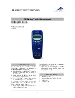
3B Netlog 1000541
Brand: 3B SCIENTIFIC PHYSICS Pages: 12


