background image

1 of 9

WX-501-0536 • 01.22

Using a Click 510

The Click 510 serves as a powerful, cabinet-level communication troubleshooting tool. It has the ability to emulate 

a SmartSensor V and to perform data integrity and data latency tests.

Note. 

With the release of version 2.0, the Click 510 is now an application that runs on the Click 500 series 

hardware platform. Some features of v2.0 operate differently than that of the v1.0 product, which had a custom 

platform. The following documentation is specific to v2.0. If you have an earlier version of the Click 510, you will 

need to refer to previous documentation. Contact Wavetronix Support for assistance.
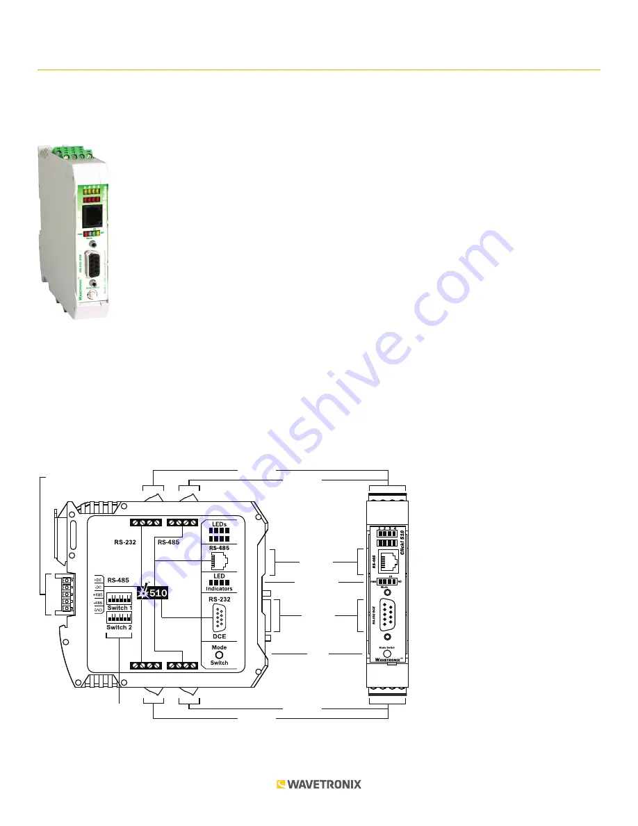
Physical Features

The Click 510 physical features are used for easy installation and configuration.

T-Bus

Connector

RS-232

Connector

RS-485

Connector

RS-232

Connector

RS-485

Connector

LED Indicators

Mode

Switch

Inputs

Connector

Outputs

Connector

DIP Switches

TOP

FRONT

0536

Summary of Contents for 0536

Page 1: ...e features of v2 0 operate differently than that of the v1 0 product which had a custom platform The following documentation is specific to v2 0 If you have an earlier version of the Click 510 you will need to refer to previous documentation Contact Wavetronix Support for assistance Physical Features The Click 510 physical features are used for easy installation and configuration T Bus Connector R...

Page 2: ...ther Click modules While it can be used to convert RS 485 communications to RS 232 this is not its normal usage Instead on the Click 510 this port is normally used to upgrade the Click 510 program or reprogram the unit for custom applications However if you are using a modified RS 232 DB 9 serial cable connector with the DTR pin removed it can be used to convert RS 485 communications to RS 232 Not...

Page 3: ...e Click 510 is installed on a T bus with active power and RS 485 If you are going to use your Click 510 in conjunction with a computer serial port and terminal program make sure there is a serial connection between the computer and the Click 510 or between the computer and another device on the same T bus as the Click 510 Remember that if you want to use the RS 232 DB 9 port on the front of the mo...

Page 4: ...en Flashing Green On with Red Flashing Autobaud Green Solid Green Solid Latency Test Yellow Solid Yellow Solid Reset Red Flashing Red Flashing Note The LED state during the mode selection process can be either flashing or solid If the current mode is a flashing mode the corresponding blue or green LED will flash during mode selection see column 2 of the table above However once a flashing mode is ...

Page 5: ... 1 second Sends data every 0 25 to 1 second Switch Sends data every time the push button is pressed Note If you would like to have the Click 510 emulate a sensor but not actively transmit any data use submenu 1 to select the Switch option As long as you don t press the push button the sensor will be passive This will allow you to use the Click 510 in conjunction with a Click 100 172 or 174 Once th...

Page 6: ...will be sent 1st LED 2nd LED 3rd LED 4th LED Submenu 1 Yellow LEDs 1 second 0 25 1 second Switch Submenu 2 Red LEDs LED flash LED sequence ASCII sequence ASCII text Test Pattern submenu 1 allows you to select when the Click 510 sends out data packets Submenu 1 selections are displayed on the device as the row of yellow LEDs see the table above 0 25 to 1 second Sends data every 0 25 to 1 second 1 s...

Page 7: ...yperTerminal 1 8 Lights up the corresponding LED on the Click 510 For example typing a 5 causes the fifth LED to illu minate The yellow LEDs are numbers 1 4 and the red LEDs are numbers 5 8 f Causes all the submenu LEDs to flash at once this is the same as LED flash on the 510 menu s Causes each submenu LED to flash in sequence this is the same as LED sequence on the 510 menu The sequence will beg...

Page 8: ...ate has been set to match the sensor The discovery process attempts all the baud rates listed in the figure above SmartSensor V autobaud discovery requests are sent at each baud rate If a response to a request is received the Click 510 baud rate will be set to match the SmartSensor baud rate Each baud rate is attempted 10 times with a longer wait time on each successive iteration During the discov...

Page 9: ...r to the tables that come up in HyperTerminal as shown in the figure below If you are not connected to the computer and want a general idea of the delay time you can refer to the submenu LEDs on the device The device will show results for each packet size starting with the 16 byte size shown by the first yellow LED When each yellow LED illuminates the corresponding delay time information will be s...

Reviews: