Wacker Neuson LTN 6K-V, Operator'S Manual
The Wacker Neuson LTN 6K-V Operator's Manual is a comprehensive guide for users of this powerful and versatile lighting tower. Providing step-by-step instructions and safety guidelines, this manual is available for free download from our website. Access the manual now and harness the full potential of your Wacker Neuson LTN 6K-V.
Share
Download


Reviews:
No comments
Related manuals for LTN 6K-V
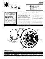
Orion
Brand: B-K lighting Pages: 2

WPX Series
Brand: G&G Pages: 5

P513.262
Brand: Gearx Pages: 37

TERES IP66
Brand: ESSE-CI Pages: 4

goLITE P2
Brand: Apollo Pages: 11

Accent Color Changing
Brand: WAC Lighting Pages: 5

Wellbi
Brand: Dayvia Pages: 72

Enel Sole ARCHILEDE HP
Brand: iGuzzini Pages: 25

super strobe
Brand: Skytec Pages: 16

18563-000
Brand: evolution lighting Pages: 3

LLEDHH03
Brand: Prime Pages: 6

Mobile Light Series
Brand: BIG ASS FANS Pages: 8

306845
Brand: Parkside Pages: 20

FOUNDATIONS Hidden Creek
Brand: Park Harbor Pages: 2

Everglade EVG9011EK
Brand: Quoizel Pages: 2

HD33681
Brand: HAMPTON BAY Pages: 4

50159560
Brand: NATURE & DECOUVERTES Pages: 2

70342
Brand: Haushalt International Pages: 4


