©Vantage, 8/17/2016 / IS-0585-B
WireLink and RadioLink DIN LVRS — MODEL: LVRS8-DIN & STOLER821
page 1 of 2
I N S T A L L A T I O N
V A N T A G E C O N T R O L S . C O M
V A N T A G E I N S T A L L G U I D E S
2168 West Grove Parkway, Suite 300, Pleasant Grove, UT. 84062 USA
Telephone: 801 229-2800
●
Fax: 801 224-0355
WireLink and RadioLink DIN LVRS — MODEL: LVRS8-DIN & STOLER821
Overview
Vantage’s DIN
Low Voltage Relay Station
WireLink™ model,
LVRS8-DIN and RadioLink™ model, STOLER821 feature 8 isolated,
latching relay channels for switching low voltage or dry contact
closures to third party systems or devices. The DIN LVRS does not
produce or provide any power. Each relay is single-pole, double-
throw, which offers a normally closed, normally open set of
contacts for each relay. Each relay has an actuator button on the
front of the LVRS which toggles the relay and is useful for testing
wiring and operation without programming the system. Some
examples for using a DIN LVRS would be: draperies, pumps, garage
doors, HVAC dampers, lifts, screens, pool covers, sprinklers,
showers, baths, security systems, etc.
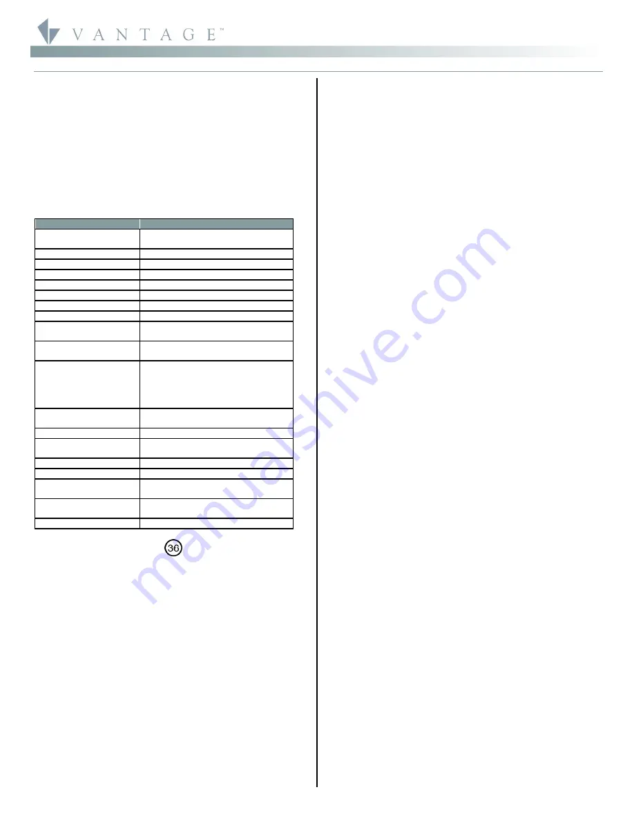
Station Specifications
Description
Specification
Dimensions, HWD
85.7mm x 157.2mm x 61.9mm
3.38” x 6.19” x 2.44”
Weight 201g
Mounting
35 mm DIN Rail (EN 50 022: 1977)
Relay Inputs
8
Relay Actuators
8
Max. Current @ Relay
1A
Max. Voltage @ Relay
48VAC / 30VDC
Min. Voltage @ Relay
0VAC / 0VDC
Lightning Surge
Protection Low Voltage
ITU-T K.20
Station Wiring
configuration
Daisy-chain/Star/Branch
Station Bus Specification
2C, 16AWG / 1.31mm2, twisted, non-
shielded, <30pF per foot. Separate a
minimum of 12" / 30.5cm from other
parallel communication and/or high
voltage runs.
Station Equivalent
InFusion
0.5W on IC-24 / 0.5W on IC-36
Station Equivalent QLink
1 Station
Station Equivalent
RadioLink
1 Station on RadioLink Systems
Station Bus connections*
24V / 36V Station Bus
LED Indicators
Status and Load State
Ambient Operating
Temperature
0-35°C / 32-95°F
Ambient Operating
Humidity
5-95% non-condensing
CE, UL and CUL Listed
YES
*
CAUTION:
36V stations have a
symbol on the Serial Number
sticker. Any station, not displaying this symbol, should not be
connected to a 36Volt Station Bus.
Software/Firmware
The WireLink model is compatible with InFusion Design Center
software or QLink 3.5 and Controller Firmware 6.5 or higher. The
RadioLink model is compatible with InFusion Design Center or
QLink 4.0 and Controller Firmware 7.0 or higher. For new projects
it is recommended that firmware and software be kept to the most
current release.
Installation/Mounting
Installation of Vantage products should be performed or
supervised by a
Certified Vantage Installer.
The Low Voltage Relay
Station installation is very simple. There are two methods of
connecting the Station Bus to the Low Voltage Relay Station for
the WireLink model:
a.
Using the 2 wire pigtail connection located on the top of the
DIN LVRS
b.
Using the pins on the side of the Station to pass Station Bus
(see Drawing) Part #VDC-0197
c.
The
RadioLink
model needs a power supply connected.
Vantage part VFA-0008, 12 Volt Plug-in Supply for use with
RadioLink Products 12VDC 1500mA is nominal.
d.
The DIN LVRS is mounted on a standard 35 mm DIN Rail
(EN 50 022: 1977).
e.
All low voltage connections to the LVRS relays are wired to
removable screw terminal connectors. These relays may be
given custom names in software to facilitate their use in the
installation.
Connecting Device Requirements
Each individual low voltage contact is rated as follows:
Maximum Current = 1A
Maximum Voltage = 48Vac / 30Vdc
Station Set Up in Software
InFusion:
First select the room, then click on
Vantage Objects
in
the
Object Explorer
and expand
Stations, WireLink
or
Stations,
RadioLink
. From the list of stations double click on the DIN LVRS to
place it in the room. In the
Object Editor,
name the station and
make sure it is on the correct station bus port.
QLink:
First change to Wiring view, right click on the Main
Controller and from the pop-up menu, select
Add DIN Stations
or
Add RadioLink Stations
|
Low Voltage Relay
from the station list.
This will reveal the
DIN Relay Station Definition
Dialog Box. Type
the name of the Station. Click OK to exit the Definition window.
Right click on the station and select Add Low Voltage Relay to add
the relay loads. In the Relay Definition window, name the relay and
assign it to the correct floor and room.
Programming the Relay Station
Because they are relays the eight buttons on the DIN LVRS cannot
be programmed directly. Programmed Buttons, Time Controls or
Host Commands in InFusion and V-Commands in QLink are used to
control the relays. The relays are accessed by selecting the relay
load in Programming.
Configuration with Wired Models
When the station is first connected to the Station Bus, the
diagnostic LED will blink twice followed by a pause, meaning that
the station is connected correctly but not yet configured. From
Design Center, click on the Configure Stations button on the
toolbar or from QLink, select System | Configure Stations and click
on the radio Configure button in the Online Configuration section
from the pull down menu. Highlight the DIN LVRS. The Status LED
will blink 5 times followed by a pause and the button LEDs will
blink rapidly indicating that the station is in configuration mode. To
finish configuring press any button on the Station 3 times. The
station may also be configured by typing the serial number in the
project file, using this method the station will automatically be
configured when the system is programmed. Once configured the
Status LED will blink evenly and the buttons stop blinking.
Configuration with RadioLink*
RadioLink DIN LVRSRL stations need to be configured to associate
which physical station goes with the station in software.
When the station is initially powered-up, the Status LED will blink
three times followed by a pause - this means the station is
powered correctly but not yet on the network.
Before
uploading
the file to the Vantage system, do the following: From Design
Center, click in the
Serial Number
section in the
Object Editor
and
type in the serial number. From the menu bar in QLink, select
System/Configure Stations
. A list of all stations will be displayed on
the screen. Manually enter the serial number for each RadioLink
station to match it with the corresponding programming in QLink.
The serial number of each station is located on a permanent sticker
on the front of the station. Record the number for easy reference
when programming. The Main Controller will add to its network
and configure all the RadioLink stations that it has serial numbers
for. This may take several minutes depending on the number of
RadioLink stations on the network. The Status LED will blink
steadily when a station has been added to the network and
configured.