background image

Document:   GF07Z303 Rev 1

INSTRUCTION MANUAL

INSTALLATION - OPERATION - MAINTENANCE

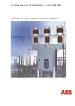
HV6FS Vacuum Circuit Breakers – Fixed Type
4.8 & 7.2kV Voltage Classes

(Fast Closing)

APPLICABLE MODEL NUMBERS:

(Motor Operation Types)

HV6FS-MU
HV6FS-ML

Issued: 8/2004

Phone: 800.894.0412 - Fax: 888.723.4773 - Web: www.clrwtr.com - Email: [email protected]

Summary of Contents for HV6FS

Page 1: ...OPERATION MAINTENANCE HV6FS Vacuum Circuit Breakers Fixed Type 4 8 7 2kV Voltage Classes Fast Closing APPLICABLE MODEL NUMBERS Motor Operation Types HV6FS MU HV6FS ML Issued 8 2004 Phone 800 894 0412 Fax 888 723 4773 Web www clrwtr com Email info clrwtr com ...

Page 2: ...Phone 800 894 0412 Fax 888 723 4773 Web www clrwtr com Email info clrwtr com ...

Page 3: ...d Service Department Toshiba International Corporation 13131 West Little York Road Houston Texas 77041 USA or call 713 466 0277 800 231 1412 800 527 1204 Canada Fax 713 466 8773 Please complete the following information for your records and retain with this manual Model ___________________________________ Serial Number _____________________________ Date of Installation _________________________ In...

Page 4: ...Phone 800 894 0412 Fax 888 723 4773 Web www clrwtr com Email info clrwtr com ...

Page 5: ...llow instructions Severe property damage might also occur Means that you might be injured if you do not follow instructions Equipment damage might also occur NOTE Gives you helpful information Note The contents of this manual will not become apart of or modify the warranty policy The terms of which are set forth at the end of this manual READ SAFETY SIGNS To avoid injury you must read and follow a...

Page 6: ...ractices 4 Be trained and authorized to perform the service maintenance or repair of this equipment 5 Be trained in the proper care and use of protective equipment such as rubber gloves hard hat safety glasses face shield flash clothing etc in accordance with established practices 6 Be trained in rendering first aid SAFETY CODES Toshiba HV6FS vacuum circuit breakers are designed and built in accor...

Page 7: ...rty damage Turn off and lock out Primary and Control Circuit Power before servicing Keep all panels and covers securely in place Never Defeat Modify or Bypass any Safety Interlocks Qualified Operators only DANGER Phone 800 894 0412 Fax 888 723 4773 Web www clrwtr com Email info clrwtr com ...

Page 8: ...ns 16 Ground Connections 17 Control Circuit Connections 18 PRE ENERGIZATION CHECK 19 General 19 Electrical Checks 19 OPERATION 20 Manual Operation 20 Electrical Operation 21 Undervoltage Trip 25 MAINTENANCE 26 Maintenance Program 26 Maintenance Record 26 Servicing Equipment 26 Inspection and Maintenance Types 27 Table 1 Tightening Torques 27 Table 2 Check Points for Periodic Inspection 28 Vacuum C...

Page 9: ...BLE OF CONTENTS Page 5 Table 3 Ratings Manual Operation HV6FS MU and HV6FS ML Types 34 WARRANTY AND LIMITATION OF LIABILITY 35 Phone 800 894 0412 Fax 888 723 4773 Web www clrwtr com Email info clrwtr com ...

Page 10: ...Page 6 Phone 800 894 0412 Fax 888 723 4773 Web www clrwtr com Email info clrwtr com ...

Page 11: ...of interest as follows GENERAL DESCRIPTION Provides a description of the equipment information on major components and how they function plus rating information RECEIVING INSPECTION AND HANDLING Describes procedures for receiving unpacking inspecting handling lifting and moving the circuit breaker INSTALLATION Provides information on installing the circuit breaker in the switchgear cell along with...

Page 12: ... upon command Both types can be tripped electrically and also include undervoltage release Arc interruption is accomplished inside sealed vacuum interrupters mounted on track resistant insulators Vacuum interrupters use low surge contact materials that exhibit low current chopping levels reducing switching overvoltages Fig 1 and Fig 2 illustrate and identify the major components of the circuit bre...

Page 13: ...ndication is ON the main contacts are closed 2 Closing Spring Status Indicator Indicates if the closing springs are CHARGED Yellow or DISCHARGED White 3 Manual Charging Handle Turn the handle clockwise 3 to 5 times will charge the closing spring Closing Spring Status Indicator changes to CHARGED Yellow When the handle is released it returns to its normal position and do not attempt to turn again 4...

Page 14: ...sufficiently to check for missing parts or concealed damage 3 Check for the presence of accessories that are shipped with the circuit breaker Charging Handle shipped loose with MU and ML type breakers Fig 4 Insulating cylinders qty 6 Fig 5 3 Keep the circuit breaker upright Never lay the circuit breaker on its side or upside down This may cause damage 4 File a claim with the carrier for any damage...

Page 15: ...to avoid damage to the equipment and personal injury Always keep the circuit breaker in a generally upright position Refer to Fig 6 and Fig 7 for the correct methods of lifting and moving the circuit breakers Fig 6 Correct Method for Handling the MU Type Circuit Breaker Fig 7 Correct Method for Handling the ML Type Circuit Breaker Phone 800 894 0412 Fax 888 723 4773 Web www clrwtr com Email info c...

Page 16: ...to Installation the maximum fault current capacity of the power system at the point of installation should be verified This value must not exceed the symmetrical interrupting capability of the circuit breaker Fig 8 illustrates a typical circuit breaker nameplate Do not exceed the ratings specified on the circuit breaker nameplate or system accessories Underrated equipment can fail during operation...

Page 17: ...te and breaker and discard them make sure none are left inside the breaker 3 Align the breaker with the cutout and mounting holes on the panel to which it is to be mounted Fig 10 Some breakers are furnished with two hooks that may be used to temporarily attach the breaker to the panel 4 Using the four M8 bolts removed in step 2 fasten the breaker and its front plate to the mounting panel Fig 11 Th...

Page 18: ...NSTALLATION Fig 12 Panel Cutout Dimensions 10 71 0 38 RADIUS 4 PLACES 0 343 DIA 4 PLACES 0 25 0 25 0 25 0 25 8 03 Dimensions in Inches Phone 800 894 0412 Fax 888 723 4773 Web www clrwtr com Email info clrwtr com ...

Page 19: ...FF green then mount it by following the steps below 1 Fasten the breaker onto steel angles or to a flate plate Fig 13 Use M8 hex head bolts either 50 mm or 35 mm The tightening torque should be 120 150 kgf cm 9 11 ft lb 2 Either mounting method shown in Fig 14 may be used Fig 13 Mounting Breaker to Flat Plate or Angles Fig 14 Optional Hardware Orientation ANGLE PANEL M8 x 35MM OR M8 x 50MM BOLT Ph...

Page 20: ... Follow the manufacturer s installation instructions provided with the termination kit To connect cables follow the steps below 1 Pass the cable through the insulating cylinder six cylinders are supplied with the circuit breaker Fig 15 2 Fasten the cable to the main circuit terminal Fig 16 Use 35 mm Class 8 8 M10 or M12 hex head bolts 2 flat washers a lock washer and a nut While securely preventin...

Page 21: ...the ground terminal is on the left side of the operating mechanism as viewed from the rear of the breaker To make the ground connection first remove the fastening M6 hex head bolt and crimp on terminal provided with the breaker and crimp the terminal to the end of the ground wire Fig 18 Then reattach the terminal using the same bolt previously removed and torque to 50 65 kgf cm 43 56 in lb For ML ...

Page 22: ...f this manual On the MU type breakers connections to auxiliary contacts are made directly to the auxiliary switch Fig 21 On the ML type breakers connections to auxiliary contacts are made to a terminal block on top of the operating mechanism Fig 22 Fig 20 Connection to Control Terminal Block Fig 21 Auxiliary Contact Connections on MU Type Breakers Fig 22 Auxiliary Contact Connections on ML Type Br...

Page 23: ...ver from installation must be cleaned out Cover all unused openings Install all panels guards and covers A supply of spare parts should be established Instruction manuals and diagrams should be collected and filed ELECTRICAL CHECKS Electrical shock hazard Do not touch energized components during a test using auxiliary power An electrical insulation resistance test should be performed to verify tha...

Page 24: ...the closing spring status indicator shows DISCHARGED white Turn the charging handle clockwise 3 to 5 times to charge the closing spring Fig 23 Closing Spring Status Indicator changes to CHARGED Yellow When the handle is released it returns to its normal position and do not attempt to turn again If the closing spring status indicator shows CHARGED yellow Do not attempt to turn handle Pushing the Gr...

Page 25: ... in Fig 28 through Fig 29 for determining external control circuit connections to the circuit breaker Fig 25 Manually Opening Breaker SYMBOL DESCRIPTION M Motor TC Voltage Trip Coil CC Close Coil UV Undervoltage Trip Coil a1 to a3 Auxiliary Contacts N O b1 to b2 Auxiliary Contacts N C X Control Relay X a Control Relay Contact N O X b Control Relay Contact N C Y Auxiliary Relay Y b Auxiliary Relay ...

Page 26: ...Changes to Yellow Standby for Close Operation Close Coil Energized Circuit Breaker Closes Auxiliary Relay Closes Anti Pumping Circuit Completed Opening Signal Given Trip Coil Energized Circuit Breaker Opens Spring Status Indicator Changes to White and On Off Status Changes to ON Next Close Operation is Not Possible Unless Close Signal is Canceled On Off Status Indicator Changes to OFF Phone 800 89...

Page 27: ...OPERATION Page 23 Fig 28 125 VDC Control Circuit Schematic for MU Type Circuit Breaker Phone 800 894 0412 Fax 888 723 4773 Web www clrwtr com Email info clrwtr com ...

Page 28: ...Page 24 OPERATION Fig 29 125 VDC Control Circuit Schematic for ML Type Circuit Breaker Phone 800 894 0412 Fax 888 723 4773 Web www clrwtr com Email info clrwtr com ...

Page 29: ... relay UV When the circuit breakers are shipped the undervoltage trip device is defeated by a factory installed plug Fig 30 If this plug is left in place the circuit breaker will operate normally without power applied to relay UV Removing this plug Fig 31 activates the undervoltage trip function Fig 30 Plug Installed in UV Trip Device Fig 31 Removing Plug From UV Trip Device Phone 800 894 0412 Fax...

Page 30: ...minated insulators can allow a short circuit or ground fault to occur NOTE Refer to the SAFETY section of this manual for important information MAINTENANCE RECORD Keep a permanent record of all maintenance work At a minimum this record should include information on 1 Items inspected 2 Reports of any testing 3 Equipment condition 4 Corrective actions or adjustments 5 Date of work 6 Comments The deg...

Page 31: ...d The lubrication of sliding and rotating parts is checked and the mechanism is lubricated if needed Inspection Frequency Once every 1 3 years or every 3000 operations normal Once every 6 years detailed Refer to Table 2 for the schedule of Periodic Inspections D Unscheduled Inspection Inspections are implemented as required Inspection Frequency As needed NOTE The inspection frequency and points to...

Page 32: ...th operation Manual operation Visual inspection or touch Check lubrication Make sure moving parts operate smoothly Apply a small amount of lubrication Main Circuit Discoloration due to heat from conducting parts Visual inspection Make sure there is no discoloration Check the cause and repair Tighten connections to circuit breaker See Table 1 for tightening torques Loose bolts nuts or screws Tighte...

Page 33: ... the circuit fails to operate check the cause and repair Terminals loose or disconnected Visual inspection Tighten using a screwdriver Make sure terminals are not loose or disconnected Repair if disconnected Tighten if loose See Table 1 for tightening torques Insulation Resistance Measure ment Measure main circuit to ground Megger test at 1000V Resistance should be 500MΩ or greater Measure between...

Page 34: ...nd normal contact spacing is extremely low and well below the maximum permitted by standards As an additional safety measure however it is recommended that all personnel keep at least 1 meter 3 3 ft away from the vacuum circuit breaker while this test is performed Radiation exposure hazard X rays may cause illness or injury Stay at least 1 meter 3 3 ft away from the circuit breaker during the vacu...

Page 35: ...icient vacuum level After the test is complete discharge any residual static charge from the primary terminals of the circuit breaker If a vacuum checker or AC hi pot tester is not available a DC hi potential test may be conducted If a DC test is conducted the test voltage must be increased to 31kV DC The test duration for DC tests and the criteria for acceptance remain the same as for AC tests Do...

Page 36: ...ANCE DISPOSAL Contact your state environmental agency for details on disposal of electrical components and packaging in your particular area Phone 800 894 0412 Fax 888 723 4773 Web www clrwtr com Email info clrwtr com ...

Page 37: ...upright position INSPECTION DURING STORAGE Routine scheduled inspection is necessary if storage is for an extended period The unit should be checked for condensation moisture corrosion and vermin Prior to installation the circuit breaker should be carefully examined for evidence of physical damage corrosion or other deterioration Refer to the PRE ENERGIZATION Section of this manual The MAINTENANCE...

Page 38: ...rent kA rms 14 16 Rated Short Circuit Making Current kA crest 35 40 Rated Short Time Withstand Current 2 sec kA rms 12 5 Rated Interrupting Time 60Hz Basis cycles 3 Opening Time msec 8 25 Closing Time msec 30 Rated Control Voltage Closing Charging V DC 125 Rated Control Voltage Opening V DC 30 125 Rated Control Voltage Undervoltage Trip V AC 120 Operating Duty O 1 min CO 3 min CO Auxiliary Contact...

Page 39: ...RS AND USERS OF THE EQUIPMENT AND PARTS FOR BREACH OF THE FOREGOING WARRANTY THE COMPANY WILL HAVE NO OBLIGATIONS TO DISASSEMBLE ANY EQUIPMENT OR PART WHICH IS DEFECTIVE WITHIN THE TERMS OF THE ABOVE WARRANTY OR TO INSTALL ANY REPAIRED OR REPLACEMENT PART OR EQUIPMENT OR TO PAY ANY COSTS INCURRED IN CONNECTION WITH ANY SUCH DISASSEMBLY OR INSTALLATION THE COMPANY TOSHIBA CORPORATION AND THEIR SUPP...

Reviews: