Siemens SGIM-3268H, Manual
Looking for a user manual for the Siemens SGIM-3268H? Look no further! Our website offers a free download of the manual, providing you with the essential information you need. Simply visit manualshive.com and get your hands on the comprehensive manual without any cost involved.
Share
Download


Reviews:
No comments
Related manuals for SGIM-3268H

AKR-30S
Brand: GE Pages: 20

Series NRX
Brand: Eaton Pages: 15

Series NRX
Brand: Eaton Pages: 10

AKD6-800A
Brand: ABB Pages: 47

MB556
Brand: Stanley Pages: 36

ECONOMY SMART
Brand: Block Pages: 26

MINIA MMR-X3-001-A230
Brand: OEZ Pages: 10

1652C
Brand: Fluke Pages: 66

FC80AC
Brand: Bticino Pages: 30

183043
Brand: Eaton Pages: 16

150 VCP-WR 1500
Brand: Eaton Pages: 63

RSA-102
Brand: CBS ArcSafe Pages: 8

RRS-4
Brand: CBS ArcSafe Pages: 39
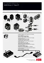
SACE Emax 2 - Tmax XT
Brand: ABB Pages: 4

AKR
Brand: GE Pages: 63


