


Manual
ECONOMY SMART
with IO-LINK
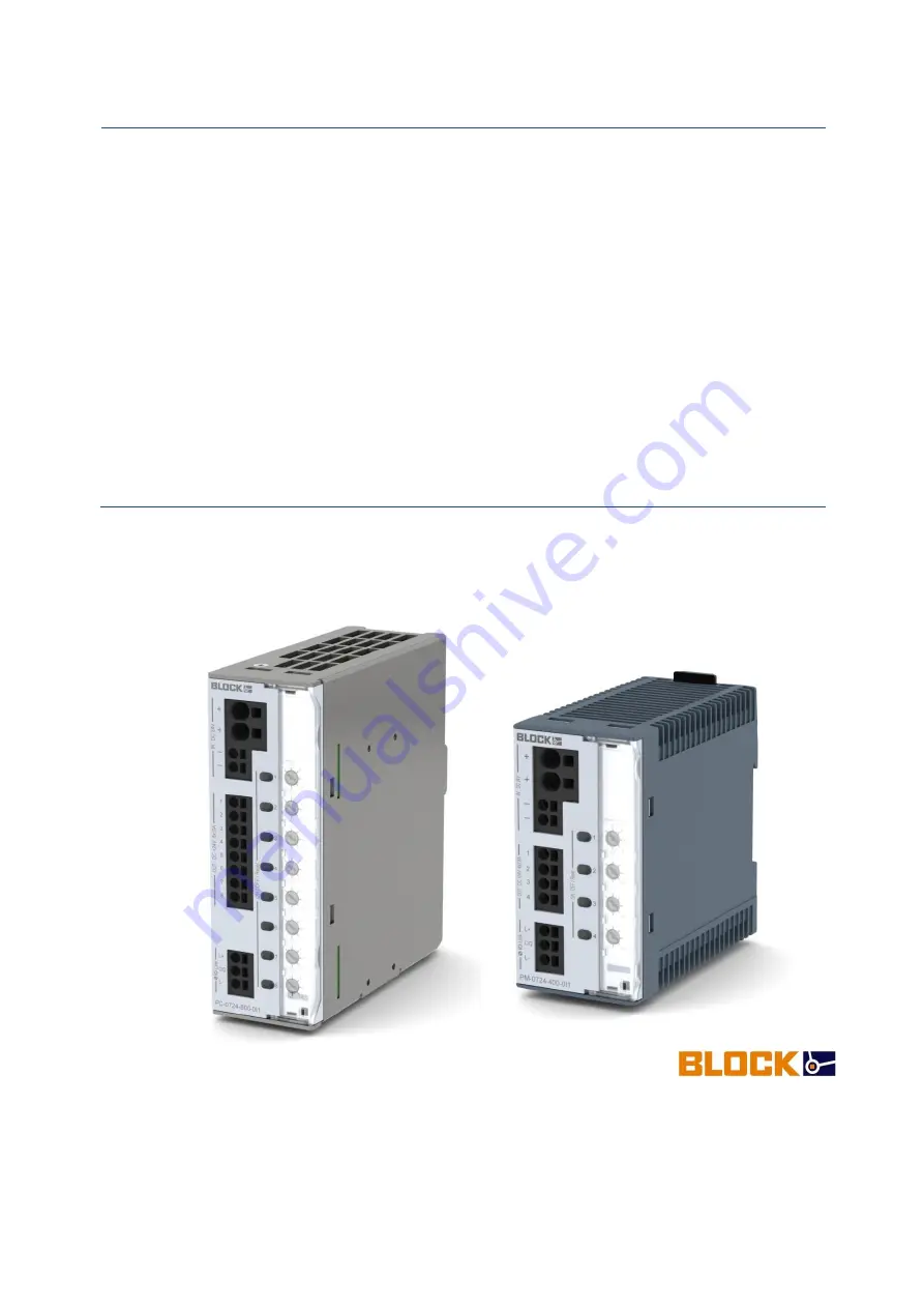
PC-0724-800-0I1
PM-0724-400-0I1
BLOCK Transformatoren-Elektronik GmbH
Max-Planck-Strasse 36–46 • 27283 Verden • Germany
Tel. +49 (0) 4231 678-0 • Fax +49 (0) 4231 678-177
[email protected] • block.eu


