

1020 - Printed in Germany
9.6600.01
Field of application
Design
Maintenance
Function description
The BA Backflow Preventer (Reduced Pressure Zone Valve) from
SYR includes all components set by EN 1717 and is designed as 3
pressure-zone-system with a controllable upstream, intermediate
and downstream pressure zone. Each pressure zone is equipped
with ball valves allowing to check each zone and to ensure the
leaktightness of the safety devices by pressure measurement. The
BA Backflow Preventer is equipped with 2 consecutive check valves
with an intermediate pressure zone in between, which can be vented
to the atmosphere. When no water is drawn off, the check valves
on either side and the drain valve are closed. In case of back-
siphonage, the inlet pressure drops. The drain valve opens at the
latest, when the differential pressure between the upstream and
intermediate zone decreases to 0.14 bar. An optical indicator allows
quick and easy verification of the Backflow Preventer's status.
Installation
Thoroughly flush the pipe prior to installation. When using the model
without shut-off valves, service valves shall be provided either side
of the Backflow Preventer. Mount the device in the pipe with the drain
valve facing downwards to ensure a perfect operation of the tundish.
Free access to the Backflow Preventer shall be provided to facilitate
maintenance works and the inspection. Do not install the device in
locations liable to frost and flooding. It should only be mounted in a well-
ventilated environment. The drain pipe's diameter shall be able to
accommodate the maximum discharge volume. We recommend installing
a potable water filter according to EN 13443, part 1 upstream of the
Backflow Preventer in order to ensure its perfect and durable
operation. Once installed, vent the device by means of the 3 ball
valves. Then, the Backflow Preventer is ready for operation.
When connecting the tundish to the sewer, comply with the requirements
set in the standard EN 12056.
The Backflow Preventer BA 6600 (or RPZ Valve) is designed to
protect potable water against non potable water up to and including
fluid category 4 in compliance with EN 1717. According to the
instructions in the national annex to EN 1717 dealing with the selection
of safety devices, the use of a BA Backflow Preventer is compulsory
for the following appliances and draw-off points in domestic and non-
domestic systems.
Softeners / ion exchangers, regeneration
Swimming pools and bathtubs with water treatment
Bath lifters, openings and operational parts above bath rim
Galvanic bath
Sterilizing of water through disinfection
Chemical mixing facilities (disinfectants or fertilizers)
Chemical cleaning system
Film developers
Printing, reprographics, photographic equipment
Filling system for heating installations (water with inhibitors)
High pressure cleaners with addition of chemical substances
Laboratory benches, chemical laboratories
Softeners / Ion exchangers, formalin disinfection
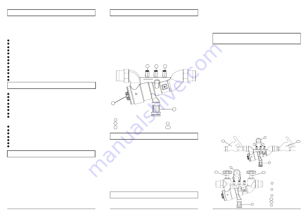
The BA Backflow Preventer is designed as follows:
Casing
Integral strainer, mesh width about 0.25 mm
Cartridge with integral check valve and drain valve
Check valve at the outlet
3 ball valves to connect a differential pressure gauge
Threaded unions
Drain connection
Available with or without stop valves
Materials
Body made of gunmetal
Cartridge of high-quality synthetic material
Check valve made of high quality synthetic material
Ball valves made of brass
Sealing elements made of NBR and EPDM
Internal parts of high quality synthetic material / brass
Drain connection of high quality synthetic material
5
4
Upstream pressure zone
Intermediate pressure zone
Downstream pressure zone
Indicator
3
2
1
4
Tundish
5
1
2
3
According to EN 1717, the Backflow Preventer has to be serviced
on a regular basis. Therefore maintenance agreements between
user and installer are very useful. The correct function has to be
Verification of the disconnection of the discharge
valve and the secondary check valve
service valve
inlet pressure zone
service valve
intermed. press. zone
pressure gauge
primary stop valve
drain valve
Technical specifications
secondary stop valve
1
2
3
4a
4b
5
1
2
4a
4b
5
1
2
3
4a
4b
5
3
Medium:
potable water
Upstream pressure:
max. 10 bar
Min. inlet pressure:
1.5 bar
Mounting position:
horizontal, drain facing downwards
Service temperature:
max. 65 °C
Drain pipe connection:
DN 50
Flow rate 6600 without service valves:
DN 32:
13.0 m³/h,
Δ
p 1.5 bar
DN 40:
20.3 m³/h,
Δ
p 1.5 bar
DN 50:
31.8 m³/h,
Δ
p 1.5 bar
Flow rate 6600 with service valves:
DN 32:
8.0 m³/h,
Δ
p 1.5 bar
DN 40:
13.0 m³/h,
Δ
p 1.5 bar
DN 50:
21.0 m³/h,
Δ
p 1.5 bar
verified after the first service year and then periodically in accordance
with the operating conditions, but every year at the latest. The ball
valves in each pressure zone allow to check the correct operation
of the valve by means of the pressure gauge (accessories; service
kit art. no 6600.00.902). The Backflow Preventer is designed with a
cartridge system, which makes the regular maintenance works simple
and unproblematic.
•
To check the discharge valve, close both shut-off valves 4a + 4b.
•
Remove the manometer plugs at the service valves 1+2.
•
Open the service valves 1+2 to depressurize the device.
•
Mount the pressure gauge's needle valves on the service valves
1+2.
•
Fit the pressure gauge.
•
Open both shut-off valves 4a + 4b.
•
Vent the device by means of both needle valves. Close them again.
•
Close the shut-off valves 4a + 4b.
•
Relieve the pressure slowly by means of the needle valve 1.
•
Watch the tundish. When the first drop comes out of the tundish,
the diff. pressure shall exceed 140 mbar. If it is not the case, dirt
has accumulated in the device or there is a mechanical defect.
•
Open the needle valve 1 and discharge the intermediate pressure
zone until completely drained.
•
To verify the secondary check valve (RV2), open the outlet shut-
off valve (4b). Should water drip from the tundish, there is probably
a mechanical defect or dirt has accumulated in the secondary
check valve.
•
Close both service ball valves 1+2.
•
Remove the measuring device and put the manometer plugs back
in their position on the service valves.
•
Open both shut-off valves (4a + 4b).


