background image

D04-MEN047-00

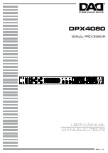
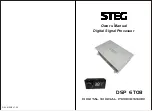
       DIGITAL SIGNAL PROCESSOR

 Ower s Manual


       Digital Signal Processor

DSP  6TO8

Summary of Contents for DSP 6TO8

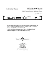
Page 1: ...D04 MEN047 00 DIGITAL SIGNAL PROCESSOR Ower s Manual Digital Signal Processor DSP 6TO8 ...

Page 2: ...ing an intergrated audio processor since thanks to the De equalization function the DSP will send back a linear signal It features selectable High and low level inputs as well as 3 5MM Aux and digital inputs that feed 8 completely variable output channels Each output channel has a 31 band equalizer available it also features a 66 freqency electronic crossover as well as BUTTERWORTH or LINKWITZ fil...

Page 3: ...h lightly damped with water 4 CONNECTION PANELS DESCRIPTION 4 1 Input signals MASTER INPUT 1 INPUTS FR FL RR RL SUB R SUB L inputs SPEAKERS The DSP comes with 6 HI LEVEL signal inputs to connect amplified signal cables coming from the main Analog source input sensitivity is adjusttable from 2 to 15V RMS 2 AUX IN L R auxiliary low level stereo input The DSP comes with an auxiliary stereo signal inp...

Page 4: ...e sure the connection polarity is as indicated on the terminals A misconnection May result in damage to the DSP After applying power wait at least 10 seconds Before turning the DSP on 2 REMOTE IN OUT REM IN input to turn on the processor remotely along with the audio signal remote Out REM OUT output to turn on other devices amplifers connected after the processor From the REMOTE IN signal the proc...

Page 5: ...TICAL OPTICAL CONTROL HIGH LEVEL INPUT CONTROL HIGH LEVEL INPUT REMOTE REMOTE CONTROL CONTROL AUX IN AUX IN GND GND 12V 12V REM IN REM IN REM OUT 1 REM OUT 1 REM OUT 2 REM OUT 2 POWER INPUT POWER INPUT LINE INPUT LINE INPUT FL FL FR FR RL RL RR RR SUB L SUB L SUB R SUB R INPUT INPUT OPTICAL OPTICAL CONTROL HIGH LEVEL INPUT CONTROL HIGH LEVEL INPUT REMOTE REMOTE CONTROL CONTROL AUX IN AUX IN GND GN...

Page 6: ...lick NEXT 4 Choose I accept the agreement 5 Set install location 6 Create shortcut to desktop 8 Wait until the process finish 9 Installation completed reboot computer 7 Click Install to begin 7 GUI OPERATION INSTRUCTION 7 1 Guide to GUI after installation 1 Double click icon of DSP CONTROL 2 DSP connection 3 Display setup driver is not successful NO PRO ...

Page 7: ...one every signal details as experts do To bring sound effect on your beloved car to a higher level 5 When you open the DSP software interface it will pop up the following options Please click on this desktop icon Conduct install the driver 6 When you open the DSP software interface it will pop up the following options As shown in the figure please open the computer device manager Delete the excess...

Page 8: ...ssover type for example select CH selection on 3RD spot thant would locate CH you want to choose for crossover configuration 5 Save to DSP 4 CROSSOVER FREQUENCY Set frequency of LP HP individually 1 2 3 4 5 GAIN 0 40dB is optional range for gain control kf every CH CH mode click on the default in put state Output channel A B C D E F G H Input soundtrack FR FL RR RL SUB R SUBL When you click the dr...

Page 9: ...Rem Out Rem Out Front1 A B To Modbass Front1 A B To Modbass Front2 C D To Tweeter Front2 C D To Tweeter Subwoofer G H To Subwoofer Subwoofer G H To Subwoofer LTW LTW RTW RTW LMB LMB RMB RMB 4 ch Amp 4 ch Amp Rem In Rem In Relay 12 Relay 12 Rem In Rem In Monoblock Monoblock 2ch Amp 2ch Amp Subwoofer Subwoofer Ground Ground Front1 A B To FrontSpeaker Front1 A B To FrontSpeaker Front2 A B Or Rear E F...

Page 10: ...ult Midrange A B Midbass E F Subwoofer G H CONNECTION From To Personal Computer 1 x USB B 1 1 2 0 5M CROSSOVER N 5 one each output channel Filter Type Full High Low Pass Band Pass Slope Setting 6 12 18 24 30 42 48 dB 68 steps 20 20kHz Phase control indepent setting for each channel 0 180 Crossover frequency Subwoofer Subwoofer Ground Ground Front1 A B To Midrange Front1 A B To Midrange Subwoofer G...

Reviews: