SBG GeoStar 200, User Manual
The SBG GeoStar 200 is a cutting-edge GPS device designed for accurate and reliable positioning. Ensure you make the most of your device by downloading the User Manual for free from manualshive.com. This comprehensive manual will guide you through the setup and operation of your GeoStar 200.
Share
Download


Reviews:
No comments
Related manuals for GeoStar 200

Univerge DT820
Brand: NEC Pages: 27

MorphoAccess SIGMA Series
Brand: Safran Pages: 32

VariPOS
Brand: Poindus Pages: 40

P4WW-24TXH-A
Brand: NEC Pages: 28

701 RF
Brand: Worth Data Pages: 155

SAFRAN
Brand: MORPHO Pages: 34

UC-230
Brand: Hanchang System Pages: 14

CV100
Brand: CoComm Pages: 34

P 27000 H1-S011
Brand: Knick Pages: 24

240
Brand: J2 Pages: 36

TC-1511-IP
Brand: CommScope Pages: 9

HBA127H
Brand: hager Pages: 4

ProFace X
Brand: ZKTeco Pages: 97

HT680
Brand: Unitech Pages: 75

MR350 MKII
Brand: Unitech Pages: 92
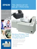
TM-J9000 Series
Brand: Epson Pages: 2

TM-T70
Brand: Epson Pages: 2

TM-T70
Brand: Epson Pages: 13


