background image

www.RIEVTECH.com

Installation and wiring
Programming
Configuring software
Applications
Technical data

RIEVTECH

USER MANUAL

+ Programming guide

Ver. 2.0.0.1

Summary of Contents for PR-12 Series

Page 1: ...www RIEVTECH com Installation and wiring Programming Configuring software Applications Technical data RIEVTECH USER MANUAL Programming guide Ver 2 0 0 1...

Page 2: ...introduction 11 2 1 Naming Rules of PR Series PLC 11 2 2 Hardware model selection 11 2 3 Structure dimension 13 3 Installing removing xLogic 16 Dimensions 16 3 1 DIN rail mounting 17 3 2 Wall mounting...

Page 3: ...LAD 58 5 5 4 How to input commands in LAD 58 5 5 5 How to enter the address in LAD 60 5 5 6 How to edit program elements in LAD 60 5 5 7 How to use find replace 63 5 5 8 How to display errors in LAD i...

Page 4: ...to double integer 92 6 5 4 Integer to string 92 6 5 5 Double integer to integer 94 6 5 6 Double integer to real number 94 6 5 7 Double integer to string 95 6 5 8 BCD to integer integer to BCD conversi...

Page 5: ...3 ATCH 144 6 9 4 DTCH 146 6 9 5 Clear interrupt event 148 6 10 Logic operation 149 6 10 1 INV B 149 6 10 2 INV W 150 6 10 3 INV DW 151 6 10 4 WAND B WOR B WXOR B 152 6 10 5 WAND W WOR W WXOR W 153 6 1...

Page 6: ...7 6 15 Table 188 6 15 1 Last in first out 188 6 15 2 FIFO 190 6 15 3 Add to table 192 6 15 4 Memory fill 194 6 15 5 Table Find 195 6 16 Timer 197 6 16 1 Switch on delay timer 197 6 16 2 TONR 199 6 16...

Page 7: ...o switch PLC mode 231 10 2 Value range of analog quantity 232 10 3 Extension module address 232 10 4 PLC host address range 233 10 5 Formula 233 10 6 Set extension module address with a dial switch 23...

Page 8: ...ur application The xLogic Micro PLC is available in 120V 240V AC or 12V and 24V DC versions making it the ideal solution for relay replacement or simple control applications as building and parking lo...

Page 9: ...according to the degree of danger Caution Indicates that death or severe personal injury may result if proper precautions are not taken Caution With a safety alert symbol indicates that minor personal...

Page 10: ...Rievtech does not accept any liability for possible damage to persons buildings or machines which occur due to incorrect use or from not following the details Prescribed Usage Note the following Warni...

Page 11: ...ved Disclaim of Liability We have reviewed the contents of this publication to ensure consistency with the hardware and software described Since variance cannot be precluded entirely we cannot guarant...

Page 12: ...simple control applications such as building and parking lot lighting managing automatic lighting access control watering systems pump control or ventilation systems in factory and home automation and...

Page 13: ...memory capability Not applied to PR 6 PR 12 E series CPU l RS232 and USB communication download cable with photo electricity isolation l Support ladder diagram programming Not applied to PR 6 PR 12 E...

Page 14: ...ons Special versions without operator panel and display unit are available for series production applications in small machine installation and cabinet building environments to further slash cost 1 4...

Page 15: ...through xLogicsoft for running It also is the connection cable between CPU and third party device with the RS232 port just like HMI in modbus communication system l xLogic USB communication cable Mod...

Page 16: ...I protocol Note PR RS485 module is required to connect the CPU to RS485 BUS RS232 or USB port ELC ES232 ELC USB needed If there is no network required and only one main module with some expansion modu...

Page 17: ...10 Note xLogic CPU may be equipped with expansion modules of the different voltage class but expansion module must be supplied the correct power corresponding to its type...

Page 18: ...10V 4 digital 4Transistor 0 3A PNP 4 I5 I8 60KHZ Yes 10KHZ yes yes PR 14 Series CPU Units Expandable built in RS485 port Model Expansion Supply voltage Inputs Outputs High speed count PWM HMI RTC PR...

Page 19: ...10A 4 relays 3A PR E 16DC DA TN DC12 24V 4digital 4analog 0 10V digital 8 transistors PNP 0 3A PR E PT100 DC12 24V 3 Channels PT100 resolution 0 5 temperature range 50 200 none PR E AQ VI DC12 24V no...

Page 20: ...e used as RS232 port with ELC RS232 or RS485 port with PRO RS485 3 HMI LCD panel 4 keypad 5 Output terminals 2 PR 14 and PR 18 series model 1 Power supply Input terminals 2 HMI LCD panel 3 keypad 4 Ou...

Page 21: ...14 Dimensions of PR 14 and PR 18 3 PR 24 series CPU 1 Power supply 2 Input 3 Program RS232 port 4 HMI LCD panel 5 keypad 6 Extension RS485 port 7 Output...

Page 22: ...E extension module 1 Power supply Input terminals 2 Connection cable between CPU and extension Detached 3 Extension port left 4 RUN STOP indicator 5 Extension port Right 6 Output terminals Dimensions...

Page 23: ...mounted to 35 mm DIN rails to EN 50022 or on the wall xLogic width l PR 14 PR 18 Series CPU has a width of 95mm l PR E expansion modules have a width of 72mm l PR 24 Series CPU has a width of 133mm l...

Page 24: ...ge 6 Remove the plastic cover in the expansion port of CPU and expansion module 7 Plus the connector on the flat cable to CPU Repeat the expansion module steps to mount further expansion modules Note...

Page 25: ...profile rail Repeat steps 1 to 4 for all other expansion modules 3 2 Wall mounting For wall mounting first slide the mounting slides on the rear side of the devices towards the outside You can now wa...

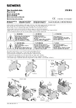
Page 26: ...19 1 xLogic CPU PR 12 Series CPU PR 14 and PR 18 series 1 PR 18 CPU 2 PR E extension...

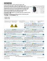
Page 27: ...20 PR 24 series...

Page 28: ...he terminals after you have completed the installation To protect xLogic adequately from impermissible contact to live parts local standards must be complied with 3 4 Connecting the power supply ThePR...

Page 29: ...u connect sensor elements such as momentary switches switches light barriers daylight control switches etc AC Type DC Type Signal status 0 Input current 40VAC 0 03mA 5VDC 0 1mA Signal status 1 Input c...

Page 30: ...23 2 Connecting xLogic is shown as in the following figures DC type digital inputs AC type digital inputs Analog Inputs DC 0 10V Analog inputs current Inputs 0 20mA...

Page 31: ...the terminals M1 and IC1 this rule also shall be applied to M2 and IC2 M3 and IC3 would be short connected Such connection can not compensate error tolerance caused by the resistance in measurement l...

Page 32: ...elay output Various loads such as lamp fluorescent tube motor contact etc can be connected to the outputs of xLogic The maximum ON output current that can be supplied by xLogic is 10A for the resistan...

Page 33: ...ot exceed 0 3A When the switch is ON Q 1 the maximum current is 0 3A Notes PNP The load connecting voltage must be 60VDC and it must be DC The terminal of the output wiring must be connected with the...

Page 34: ...bringing out 3 wiring terminals short circuited inner of such 3 terminals so only one channel RS485 bus is available from RS485 port 2x8pin of CPU PR 18 ELC 22 PR 24 for your easy connection with oth...

Page 35: ...amming port RS232 port RS232 cable USB cable ELC MEMORY ELC BATTERY PRO RS485 should be inserted in this port When the programming port should be used as the standard RS232 port D shape 9 pin header t...

Page 36: ...B 4 GND 6 GND 7 CANL 9 CANH 15 5V 16 5V Communication between CPU and expansion module will use 4 7 9 15 pin PR RS485 module is required when PR 18 PR 24 CPU communicate with the third party devices...

Page 37: ...et to 1 when a LIFO or FIFO instruction attempts to read from an empty table Not_BCD SM1 6 Set to 1 when an attempt is made to convert a non BCD value to a binary value Not_Hex SM1 7 Set to 1 when an...

Page 38: ...ent PLC are different PR 24DC DA R PLC and PR 24DC DAI RTA PLC have four high speed counters The input points of high speed counters are I1 0 I1 1 I1 2 and I1 3 HCO HC1 HC2 HC4 are used for storing th...

Page 39: ...P to open Save Save the current edit program you can use the shortcut CTRL S to save Save as You can save the project and you can save the project with other names which have been saved Save as binar...

Page 40: ...nd place it in the WINDOWS clipboard buffer Copy Select the object copy the operation and the copy of the object is placed in the WINDOWS clipboard buffer Paste Stick the cut or copied object in the s...

Page 41: ...of the module in the instruction tree Symbolic addressing After the start symbol editing function it will display the symbol of the annotation Toolbar The toolbar of the contents are as follows You ca...

Page 42: ...PLC Compile Compile the program of the current page Compile all Compile all project components program block data block and system block Clear Clear all the data in the PLC only offline can clear the...

Page 43: ...PLC data In offline state does not represent the state of STOP in PLC if you want to make STOP in PLC state you can modify the state of PLC in the connection state in offline state can not be modified...

Page 44: ...ry to the function of the undo 5 2 6 Cut Select an object cut it and place it in the WINDOWS clipboard buffer 5 2 7 Copy Select the object copy the operation and the copy of the object is placed in th...

Page 45: ...operation can not be carried out 5 2 20 Normally open contacts Click to select the normally open contact in the program editing area will appear normally open contact which is undefined you can click...

Page 46: ...rs are capital 5 2 26 Level The instruction and function blocks are connected in series 5 2 27 Vertical line The instruction and function blocks are connected in parallel 5 2 28 Take back When the ena...

Page 47: ...40 5 3 Instruction tree...

Page 48: ...ta blocks for programmers to use The contents of the data block are as follows In the data block you can set the address data type data value and annotation The contents of the data blocks are written...

Page 49: ...he following interface RS232 RS485 interface All ports are using MODBUS communication protocol You can set four ports They are port 0 port 1 port 2 and port 3 You can set the station number baud rate...

Page 50: ...43 CAN interface PLC supports CAN communication CAN communication will be introduced in the communication block...

Page 51: ...can t upload the PLC program Then you have to enter a password before using each function of PLC And if you forget the password 1 Power off PLC 2 Keep pressing the UP key and ESC key then power up to...

Page 52: ...e select the storage area you want to keep You can define the address holding range in the following storage areas As the following V M C and T For timers only the memory timer TONR can be kept and on...

Page 53: ...t time parameter setting interface There are two time interrupt events respectively the time of the interrupt event 1 and the time of the interrupt event 0 The interrupt time you can set is 1 to 255 m...

Page 54: ...47 Force table interface When PLC is converted from RUN mode to STOP mode the selected output points will be 1...

Page 55: ...m Check the subroutine right click to add or delete subroutine The main program can not be added or deleted 5 3 5 Function symbol Double click the function symbol the pop up interface is as follows Yo...

Page 56: ...ck the status chart the pop up interface is as follows In the status chart you can set the address data type value and forced 5 3 8 Cross reference The cross reference displays the address symbol loca...

Page 57: ...is as follows Serial Port You can set the station number port baud rate parity and stop bit MODBUS PLC doesn t support the MODBUS TCP IP function temporarily CAN KVASER CANPRO CANALSYT II are three k...

Page 58: ...51 5 3 10 Instructions Instructions will be explained in detail in the instructions section...

Page 59: ...m editor Local variable table It will be described in detail in the PLC X Ladder storage area and variable Program editing area In the program editing area the main program interrupt program and subro...

Page 60: ...chart information output Status Chart 5 3 7 chapter Information Output The output information window keeps a list of errors generated during compilation When program modification is completed compile...

Page 61: ...ctions and stores the data in different memory areas C performs all communication requests D PLC performs CPU self test diagnostic program PLC ensure that the hardware program memory and all expansion...

Page 62: ...the POU of the local variable Each POU has a separate local variable table Attention if you use the same address name in the local and global variables table local variables are preferred Local varia...

Page 63: ...put the unconditional END MEND RET or RETI into the program the compiler will return an error message subroutine Subroutine is particularly useful when you want to perform a function repeatedly You j...

Page 64: ...ject Click the file icon select open or open the PWM file 5 5 2 Ladder logic element and its working principle Ladder logic LAD is a graphical language which is similar to the electrical relay diagram...

Page 65: ...ed to the out of block This means that you can place more instructions behind the block In the network you can connect in series with a number of boxes with ENO If there is no ENO in the box no instru...

Page 66: ...in the program editor window Click the mouse there will be a selection box 1 Select the required button in the toolbar Or use the functional keys F4 contacts F6 coil F9 box 2 The second step is over...

Page 67: ...n Because the compiler will automatically specify the L memory address you do not have to enter the address for the local variable You can drag the edge of the table to minimize the size of the local...

Page 68: ...lls instructions addresses and networks 1 Select an empty cell you can use the right key to select the operations as follows 2 Select an instruction you can use the right key to select the operations...

Page 69: ...n use the DELETE or BACKSPACE key to delete the cells You can select the elements that need to be deleted use the right key to select the delete function component Attention in order to select the ver...

Page 70: ...Enter the string you want to replace in the replacement content field 3 To find the next string click the Next button 4 If you want to replace the string click replace If you want to replace all of t...

Page 71: ...enu to compile Compile Allows you to compile a single element of the project When you select compile the current window is compiled and the other windows are not compiled All compile Compiles the prog...

Page 72: ...ings How to build a communication between the personal computer and the PLC in the Xladder It depends on the hardware that you installed Use the communication cable to connect PLC and the computer set...

Page 73: ...66 2 Select the PLC model ensure that the PLC model in the software is consistent with the actual PLC model...

Page 74: ...ogram to PLC Steps are as follows Attention the new program will cover the old program 1 Before the program is downloaded to PLC the program needs to be compiled 2 After the success of the compiler cl...

Page 75: ...on the software will display a warning message 7 You can double click on the project of the project manager to modify the PLC model 8 Click the download button to download the program again 9 If the p...

Page 76: ...State monitoring shows the current value of the PLC data and the information of the current state You can monitor read write and enforce PLC data values by using the status table When the program runs...

Page 77: ...ate display Attention If the program downloads successfully you have to convert the PLC from the STOP mode to the RUN mode to run the program Because in STOP mode you will not be able to see the expec...

Page 78: ...Click the run button to execute the RUN mode Or click the stop button to execute the STOP mode 2 Select the PLC run menu command to execute the RUN mode Or select PLC stop menu command to execute the...

Page 79: ...d write immediately functions I O points can be forced and other storage areas can not be forced Cancel the mandatory Select unforced in the status table to cancel mandatory How to perform a limited n...

Page 80: ...osed contact Normally open contact a contact that is open in nature Normally closed contact a contact that is closed in nature The output is represented by a symbol called a coil The blocks are functi...

Page 81: ...criptions 6 1 Bit logic 6 1 1 Normally open and normally closed Input output Operand Data type Bit LAD STL I Q M SM T C V S L Boolean Input FBD I Q M SM T C V S L Enable bit Boolean Output FBD I Q M S...

Page 82: ...s disconnected When the bit is equal to 0 the normally open contact is disconnected and the normally closed contact is closed In STL the normally open contact is represented by LD And and Or instructi...

Page 83: ...the actual input point is 1 normally open immediate is closed When the actual input point is 0 normally closed immediate is closed In LAD normally open immediate and normally closed immediate instruc...

Page 84: ...utput FBD I Q M SM T C V S L Enable bit Boolean When left logic is converted from 0 to 1 Rising edge contact conduction time is a scan cycle When left logic is converted from 1 to 0 Falling edge conta...

Page 85: ...output instruction writes the new value of output bit to process image register In LAD and FBD when the output instruction is executed the PLC will open or close the output bit in the process image re...

Page 86: ...t Operand Data type Bit I Q M SM T C V S L Boolean N VB IB QB MB SMB SB LB AC constant VD AC LD Byte Set instruction can make a bit or a series of bits be 1 Reset instruction can make a bit or a serie...

Page 87: ...rated by executing the instruction is written to the actual output and the corresponding process image register 6 1 9 SR instruction Input output Operand Data type S1 R LAD Enable bit Boolean S1 R FBD...

Page 88: ...C V S L Enable bit Boolean OUT LAD Enable bit Boolean OUT FBD I Q M SM T C V S L Enable bit Boolean xxx I Q M V S Boolean Bistable trigger is a latch When both R1 and S are equal to 1 the output is 0...

Page 89: ...82 Example 6 1 11 NOP instruction NOP instruction is invalid for user program execution Can not use NOP instruction in FBD mode The value of N is between 0 and 255...

Page 90: ...o the time buffer of 7bytes starting at the address T The TODW instruction writes the current time and date to the hardware clock that is specified by the 7 bytes time buffer at the beginning of the T...

Page 91: ...struction reads the PLC port site from the PORT and put the value in the address specified in the ADDR 6 3 2 Set port address Input output Operand Data type ADDR VB IB QB MB SB SMB LB AC Constant VD L...

Page 92: ...instructions are used for comparing two values IN1 and IN2 Comparison includes IN2 IN1 IN2 IN1 IN2 IN1 IN2 IN1 IN2 or IN1 IN2 Byte comparison without symbol In LAD the contact is open when the result...

Page 93: ...86 2 Enter the illegal real number Example...

Page 94: ...on includes IN1 IN2 IN1 IN2 IN1 IN2 IN1 IN2 IN1 IN2 or IN1 IN2 Integer comparison with symbol 16 7FFF 16 8000 In LAD when the comparison result is true the contact will be open In FBD when the compari...

Page 95: ...parison includes IN1 IN2 IN1 IN2 IN1 IN2 IN1 IN2 IN1 IN2 or IN1 IN2 Double integer comparison with symbol 16 7FFFFFFF 16 80000000 In LAD when the comparison result is true the contact will be open In...

Page 96: ...IN2 Comparison includes IN1 IN2 IN1 IN2 IN1 IN2 IN1 IN2 IN1 IN2 or IN1 IN2 Real number comparison with symbol In LAD when the comparison result is true the contact will be open In FBD when the compari...

Page 97: ...ect address 2 Enter a string of more than 254 characters in length 3 The start address and length of the string cannot be put into a specified memory area ASCII constant string data type format String...

Page 98: ...AC VD LD Byte OUT VW IW QW MW SW SMW LW AQW T C AC VD LD AC Integer Byte to integer The B I instruction converts the byte value to the integer value and the result is inserted into the variable speci...

Page 99: ...utput will not be affected 6 5 3 Integer to double integer Input output Operand Data type IN VW IW QW MW SW SMW LW T C AIW AC constant VD LD AC Integer OUT VD ID QD MD SD SMD LD AC VD LD AC Double int...

Page 100: ...e format of the string data type The length of a string can be between 0 and 254 characters The maximum length of the string is 255 bytes String length Character 1 Character 2 Character 3 Character 4...

Page 101: ...d the result is inserted into the variable specified by the OUT Large value will result in overflow and the output will not be affected 6 5 6 Double integer to real number Input output Operand Data ty...

Page 102: ...ng that is the number of characters If a constant string is entered directly into the program editor or data block the string must start and end with double quotation marks string constant The followi...

Page 103: ...type IN LAD FBD VW IW QW MW SW SMW LW T C AIW AC constant VD AC LD word OUT VW IW QW MW SW SMW LW T C AC VD LD AC word The BCD I instruction converts the binary coded decimal value to the integer val...

Page 104: ...ber OUT VD ID QD MD SD SMD LD AC VD LD AC Double integer The ROUND instruction converts the real number value to a double integer value and the result is inserted into the variable specified by the OU...

Page 105: ...l number OUT VD ID QD MD SD SMD LD AC VD AC LD Double integer TRUNC Instruction converts 32 bits of real number to 32 bits integer and the result is inserted into the variable specified by the OUT Onl...

Page 106: ...digits Illegal format nnn 5 ssss 3 ssss Required number of characters ASCII constant string data type format String is a series of characters each character is stored as a byte The first byte of a str...

Page 107: ...mal point When the NNN value is greater than 5 or when the specified output string length is too small to store the conversion value the output string is filled with ASCII space characters The C bit s...

Page 108: ...A instruction format FMT operand definition The size of the output buffer is always 8 bytes nnn The number of characters of the right of the decimal point The effective range of the NNN is from 0 to 5...

Page 109: ...xample Example As shown in Figure The integer input is 123 nnn 1 The output value is as follows VB7 16 33 3 VB6 16 2E VB5 16 32 2 VB4 16 31 1 VB3 16 20 Space VB2 16 20 Space VB1 16 20 Space VB0 16 20...

Page 110: ...TA instruction format FMT operand definition The size of the output buffer is always 12 bytes nnn The number of characters of the right of the decimal point The effective range of the NNN is from 0 to...

Page 111: ...on format FMT operand definition The length of the output string is specified by the SSSS field 0 1 or 2 bytes are not valid The effective range of the NNN is from 0 to 5 NNN is equal to 0 the output...

Page 112: ...tes larger than nnn 6 The value in the output string must be aligned to the right Example Example Convert the real number 123 45 into ASCII code The output is 6 bytes The output VB0 VB1 VB2 VB3 VB4 VB...

Page 113: ...s starting with the out The maximum length of the ASCII string is 255 characters HEX to ASCII Instruction converts the hexadecimal digits starting with IN to the ASCII characters starting with the out...

Page 114: ...uotation marks string constant The following memory map shows the format of the string data type The length of a string can be between 0 and 254 characters The maximum length of the string is 255 byte...

Page 115: ...he following table shows examples of valid and invalid integer input strings Example Enter the string 12 45 The S I instruction converts the string from the first character and the result is an intege...

Page 116: ...ouble quotation marks string constant The following memory map shows the format of the string data type The length of a string can be between 0 and 254 characters The maximum length of the string is 2...

Page 117: ...nd invalid integer input strings Example Enter the string 123B5 The S DI instruction converts the string from the first character and the result is a double integer 123 Because B is an invalid charact...

Page 118: ...quotation marks string constant The following memory map shows the format of the string data type The length of a string can be between 0 and 254 characters The maximum length of the string is 255 by...

Page 119: ...umber and then terminates the conversion For example the string 1 234E6 will be converted to a real number value 1 234 without generating an error message The following table shows examples of valid a...

Page 120: ...IW QW MW SMW LW SW AQW T C AC VD AC LD word The low four bits value of input byte is n the nth bit of the output word is equal to 1 The other bits of the output word are set to 0 Example The low four...

Page 121: ...nt VD AC LD Word OUT VB IB QB MB SMB LB SB AC VD LD AC Byte ENCO The nth bit of the input word is equal to 1 The low four bits value of output byte is n Example As shown in the above figure The 15th b...

Page 122: ...B QB MB SMB LB AC VD AC SB LD Byte SEG The instruction generates the bits of the seven segment The low four bits value of input byte is converted Seven segment code table Example Analysis The low four...

Page 123: ...le bit Boolean PV VW IW QW MW SMW LW AIW AC T C constant VD AC LD SW Integer CU bit gets a high level and the current value of the counter plus 1 When the current value is greater than or equal to the...

Page 124: ...V VW IW QW MW LW SMW AC T C AIW constant VD AC LD SW Integer The bit of CD is converted from 0 to 1 and the current value minus 1 When the current value is equal to 0 the counter is opened and counter...

Page 125: ...D AC LD SW Integer CU bit gets a high level and the current value of the counter plus 1 The bit of CD is converted from 0 to 1 and the current value minus 1 When the current value is greater than or e...

Page 126: ...D LD AC VD LD AC Real number ADD R Adding N1 and N2 the result is put into the output buffer SUB R N1 minus N2 the result is put into the output buffer N1 N2 and OUT are 32 bits of real numbers In LAD...

Page 127: ...120 Example...

Page 128: ...L R IN1 multiplied by IN2 the result is put into the output buffer DIV R IN1 divided by IN2 the result is put into the output buffer IN1 IN2 and OUT are 32 bits of real numbers In LAD and FBD IN1 IN2...

Page 129: ...D ID QD MD SMD SD LD AC VD LD AC Real number SQRT Enter a 32 bits real number IN Take IN square root and output 32 bits real number Formula OUT IN error conditions SM1 1 Overflow Special memory bits S...

Page 130: ...igonometric operations on the input radian value and put the result into OUT You can use the angle value multiplied by 1 745329E 2 to get the value of the radian The value of the input IN is radian SM...

Page 131: ...igonometric operations on the input radian value and put the result into OUT You can use the angle value multiplied by 1 745329E 2 to get the value of the radian The value of the input IN is radian SM...

Page 132: ...igonometric operations on the input radian value and put the result into OUT You can use the angle value multiplied by 1 745329E 2 to get the value of the radian The value of the input IN is radian SM...

Page 133: ...VD LD AC Real number LN Use the input value to perform natural logarithm calculation and put the result in OUT The output value 2 302585 Natural logarithm of 10 SM1 1 is used for indicating overflow e...

Page 134: ...is N and output value is e n N is a real number SM1 1 is used for indicating overflow errors and illegal values Example 5 cube 5 3 EXP 3 LN 5 125 The cube root of 125 125 1 3 EXP 1 3 LN 125 5 5 cubic...

Page 135: ...ampling time integration time differential time the last time integral term the last time the amount of the process The parameter table contains 36 bytes Offset Meaning Format Type Explain 0 PVn Proce...

Page 136: ...ial term Proportion term MPn Kc SPn PVn MPn Proportion term Kc gain SPn Set point PVn Process quantity Integral term MIn Kc Ts TI SPn PVn MIn 1 MIn Integral term Kc gain Ts Sampling time TI Integral t...

Page 137: ...130 Kc gain TD Differential time Ts Sampling time PVn 1 Last time process variable PVn Process variable...

Page 138: ...nteger OUT VW IW QW MW SW SMW T C LW AC VD LD AC Integer ADD I IN1 IN2 OUT Both input and output are 16 bits integers SUB I IN1 IN2 OUT Both input and output are 16 bits integers In LAD and FBD IN1 IN...

Page 139: ...132 Special memory bit SM1 0 Zero result SM1 1 overflow SM1 2 Negative result Example...

Page 140: ...nteger ADD DI IN1 IN2 OUT Both input and output are 32 bits integers SUB DI IN1 IN2 OUT Both input and output are 32 bits integers In LAD and FBD IN1 IN2 OUT IN1 IN2 OUT SM1 1 is used for indicating o...

Page 141: ...integer DIV IN1 IN2 OUT Input 16 bits integers and the output result is 32 bits The result includes a 16 bits remainder high and a 16 bits quotient low In LAD and FBD IN1 IN2 OUT IN1 IN2 OUT SM1 1 is...

Page 142: ...N2 OUT Both input and output are 16 bits integers DIV I IN1 IN2 OUT Both input and output are 16 bits integers Output is quotient There is no remainder If the output is larger than a word then set ove...

Page 143: ...136 Special memory bit SM1 0 Zero result SM1 1 overflow SM1 2 Negative result SM1 3 The divisor is 0 Example...

Page 144: ...tput are 32 bits integers DIV DI IN1 IN2 OUT Both input and output are 32 bits integers Output is quotient There is no remainder In LAD and FBD IN1 IN2 OUT IN1 IN2 OUT SM1 1 is used for indicating ove...

Page 145: ...AC VD LD AC Byte INC B IN 1 OUT Both input and output are 8 bits integers DEC B IN 1 OUT Both input and output are 8 bits integers The two instructions operations do not take symbols In LAD and FBD IN...

Page 146: ...nteger INC W IN 1 OUT Both input and output are 16 bits integers DEC W IN 1 OUT Both input and output are 16 bits integers The two instructions operations take with symbols 16 7FFF 16 8000 In LAD and...

Page 147: ...NC DW IN 1 OUT Both input and output are 32 bits double integers DEC DW IN 1 OUT Both input and output are 32 bits double integers In LAD and FBD IN 1 OUT IN 1 OUT The two instructions operations take...

Page 148: ...DISI If the instruction is activated all interrupts can not be used When the DISI instruction is used the interrupt events will be queued Interrupt Events I1 2 Rising edge PLC_EVENT_INPUTP0 0 Highest...

Page 149: ...142 Example...

Page 150: ...edge PLC_EVENT_INPUTP1 1 High priority Timer interrupt 0 PLC_EVENT_TIMER0 10 Low priority Timer interrupt 1 PLC_EVENT_TIMER1 11 Lowest priority Interrupt use guide Interrupt routine offers a quick re...

Page 151: ...can not be attached to the multiple interrupt routines When you attach an interrupt event to an interrupt routine the interrupt is automatically enabled When the DISI instruction is used the interrup...

Page 152: ...145 Example ATCH instruction only needs to be connected once...

Page 153: ...t events to an interrupt routine However an interrupt event can not be attached to the multiple interrupt routines When you attach an interrupt event to an interrupt routine the interrupt is automatic...

Page 154: ...147 Example...

Page 155: ...interrupt events in interrupt queue This instruction is used for removing unnecessary interrupts Interrupt Events I1 2 Rising edge PLC_EVENT_INPUTP0 0 Highest priority I1 4 Rising edge PLC_EVENT_INPU...

Page 156: ...B IB QB MB SB SMB LB AC constant VD AC LD Byte OUT VB IB QB MB SB SMB LB AC VD AC LD Byte INV B The instruction performs the complement operation to the input byte and puts the result in OUT error con...

Page 157: ...T C AIW LW AC constant VD AC LD word OUT VW IW QW MW SW SMW T C LW AC VD AC LD word INV W The instruction performs the complement operation to the input word and puts the result in OUT error conditio...

Page 158: ...D HC AC constant VD AC LD Double word OUT VD ID QD MD SD SMD LD AC VD AC LD Double word INV DW The instruction performs the complement operation to the input word and puts the result in OUT error cond...

Page 159: ...yte WAND B The instruction performs And calculation on IN1 and IN2 Then puts the result in out WOR B The instruction performs OR calculation on IN1 and IN2 Then puts the result in out WXOR B The instr...

Page 160: ...C LD word WAND W The instruction performs And calculation on IN1 and IN2 Then puts the result in out WOR W The instruction performs OR calculation on IN1 and IN2 Then puts the result in out WXOR W The...

Page 161: ...Double word WAND DW The instruction performs And calculation on IN1 and IN2 Then puts the result in out WOR DW The instruction performs OR calculation on IN1 and IN2 Then puts the result in out WXOR D...

Page 162: ...type IN VB IB QB MB SB SMB LB AC constant VD LD AC Byte OUT VB IB QB MB SB SMB LB AC VD LD AC Byte MOV B The instruction moves the input byte IN to the output byte OUT which does not change the origi...

Page 163: ...SW SMW LW T C AIW constant AC VD AC LD word integer OUT VW T C IW QW SW MW SMW LW AC AQW VD AC LD word integer MOV W The instruction moves the input word IN to the output word OUT which does not chang...

Page 164: ...t VD LD AC Double word double integer OUT VD ID QD MD SD SMD LD AC VD LD AC Double word double integer MOV DW The instruction moves the input double word IN to the output double word OUT which does no...

Page 165: ...QD MD SD SMD LD AC constant VD LD AC Real number OUT VD ID QD MD SD SMD LD AC VD LD AC Real number MOV R The instruction moves the input real number IN to the output real number OUT which does not cha...

Page 166: ...AC LD Byte N VB IB QB MB SB SMB LB AC constant VD AC LD Byte OUT VB IB QB MB SB SMB LB VD AC LD Byte These successive N bytes which start with IN are moved to OUT The range of N is from 1 to 255 error...

Page 167: ...word N VB IB QB MB SB SMB LB AC constant VD LD AC byte OUT VW IW QW MW SW SMW LW T C AQW VD LD AC word BLKMOV W These successive N words which start with IN are moved to OUT The range of N is from 1...

Page 168: ...SMD LD VD AC LD Double word N VB IB QB MB SB SMB LB AC constant VD AC LD Byte BLKMOV D These successive N double words which start with IN are moved to OUT The range of N is from 1 to 255 error condit...

Page 169: ...1 8 SWAP Input output Operand Data type IN VW IW QW MW SW SMW T C LW AC VD AC LD word SWAP The instruction interchanges high byte and low byte of the input word error conditions 0006 Indirect address...

Page 170: ...he value to OUT The process image register is not updated error conditions 0006 Indirect address 6 11 10 MOV BIW Input output Operand Data type IN VB IB QB MB SB SMB LB AC constant VD AC LD byte OUT Q...

Page 171: ...the current cycle count INDX start value INIT and end value FINAL NEXT NEXT instruction marks the end of the FOR loop and the top value of the stack is set to 1 Use FOR NEXT to set the number of loop...

Page 172: ...165 Example Notes Cycle times are set to 100 times At the end of the cycle the value of VW100 is 100...

Page 173: ...is 1 LBL instruction signs the location of n You can use the jump instruction in the main program subroutine or interrupt routine You can t jump from the main program to a subroutine or an interrupt...

Page 174: ...type n S Boolean SCR instruction is good at dealing with repetitive operations SCR load the SCR section you can use the SET instruction SCRT Jump to another SCR segment and close the current SCR segme...

Page 175: ...168...

Page 176: ...2 4 Return from subroutine RET Return from the subroutine to the main program Example Main program Subroutine When the M0 0 bit is 1 return from the subroutine the following program will no longer be...

Page 177: ...d The END instruction terminates the user program Notes You can use the END instruction in the main program but can not be used in subroutine or interrupt routine Example When the M0 1 bit is 1 the pr...

Page 178: ...171 6 12 6 STOP STOP instruction STOP Example When the M0 1 bit is 1 PLC converts to the STOP mode all the programs stop running...

Page 179: ...e careful The following programs can be performed after the scan cycle is completed 1 Communication 2 I O update except for immediate I O 3 Forced update 4 SM bits update 5 Run time diagnostic program...

Page 180: ...Input output Operand Data type IN VB IB QB MB SB SMB LB AC constant VD LD AC String If the value of EN is 1 then the LCD will display the string from IN Example When the value of M0 0 is equal to 1 th...

Page 181: ...D LD AC Byte SHR B Input byte IN and move N bits towards the right Then place the results in OUT SHL B Input byte IN and move N bits towards the left Then place the results in OUT The moved out bits a...

Page 182: ...175 Example When the value of M0 0 is 1 VB0 moves a bit towards the left and VB10 moves a bit towards the right...

Page 183: ...n place the results in OUT SHL W Input word IN and move N bits towards the left Then place the results in OUT The moved out bits are filled with zero If N is greater than or equal to 16 you can move u...

Page 184: ...ight Then place the results in OUT SHL DW Input double word IN and move N bits towards the left Then place the results in OUT The moved out bits are filled with zero If N is greater than or equal to 3...

Page 185: ...greater than or equal to 8 the remainder of N 8 is the number of rotation bits If remainder is equal to 0 Rotation operation is not performed and the value of SM1 0 is 1 If the rotation operation is...

Page 186: ...is greater than or equal to 16 the remainder of N 16 is the number of rotation bits If remainder is equal to 0 Rotation operation is not performed and the value of SM1 0 is 1 If the rotation operatio...

Page 187: ...uts the result in the output double word OUT Rotation is cyclic If N is greater than or equal to 32 the remainder of N 32 is the number of rotation bits If remainder is equal to 0 Rotation operation i...

Page 188: ...plus N shift minus N The moved out bit is placed in the overflow memory bit SM1 1 The instruction is defined by S_BIT and N error conditions 0006 Indirect address 0091 Operating number is out of rang...

Page 189: ...ditions 0006 Indirect address 0091 Operand range ASCII constant string data type format String is a series of characters each character is stored as a byte The first byte of a string defines the lengt...

Page 190: ...es of characters each character is stored as a byte The first byte of a string defines the length of the string that is the number of characters If a constant string is entered directly into the progr...

Page 191: ...126 bytes error conditions 0006 Indirect address 0091 Operand range 009B Illegal index ASCII constant string data type format String is a series of characters each character is stored as a byte The fi...

Page 192: ...ect address 0091 Operand range ASCII constant string data type format String is a series of characters each character is stored as a byte The first byte of a string defines the length of the string th...

Page 193: ...N2 in IN1 OUT is set to 0 The longest length of a single constant string is 126 bytes The longest comprehensive length of two constant strings is 240 bytes error conditions 0006 Indirect address 0091...

Page 194: ...is not found the OUT is set to 0 The longest length of a single constant string is 126 bytes The longest comprehensive length of two constant strings is 240 bytes error conditions 0006 Indirect addres...

Page 195: ...table to the output memory address Remove the last entry in the table TBL and move the value to the location specified by DATA Each time the instruction is executed the number of entries in the table...

Page 196: ...block Analysis When the value of M0 0 is equal to 1 the last entry of the table will be deleted and the value of the last entry of the table will be moved to VW300 When the value of M0 0 is equal to 1...

Page 197: ...e the value to the location specified by DATA All other entries in the table move a location upward Each time the instruction is executed the number of entries in the table reduces 1 error conditions...

Page 198: ...lock Analysis When the value of M0 0 is equal to 1 the first entry of the table will be deleted and the value of the first entry of the table will be moved to VW300 When the value of M0 0 is equal to...

Page 199: ...the table is the maximum length of the table The second value is the entry count EC it specifies the number of entries in the table Each time you add new data to the table the number of entries adds...

Page 200: ...193 When the value of M0 0 is equal to 1 The value of VW202 1 The Table will have a new entry The value of the new entry is equal to the value of VW300...

Page 201: ...nstant VD LD AC integer N VB IB QB MB SB SMB LB AC constant VD LD AC byte OUT VW IW QW MW SW SMW LW T C AQW VD LD AC integer FILL N The input value of IN is written to the OUT N continuous words The r...

Page 202: ...able Find instruction The instruction searches the same data as PTN in the table Table Find starts form the entry specified by INDX If a matching entry is found the INDX points to the entry in the tab...

Page 203: ...When the value of M0 0 is equal to 1 The table format of the Table Find begins with the entry count It doesn t have the maximum number of entries VW202 Entry Count VW204 Data 0 VW206 Data 1 VW208 Data...

Page 204: ...n the current value of the timer is equal to the preset time PT the value of the timer bit is 1 When the value of the input IN is equal to 0 timer current value is cleared TON TONR and TOF timers have...

Page 205: ...T127 100 6553 5 Attention 1 The value of each timer TXXX is different 2 The resolution of the timer depends on the time base For example the error range of the 10 millisecond timer is 10 milliseconds...

Page 206: ...me a multiple of the time base When the current value of the timer is equal to the preset time PT the value of the timer bit is 1 When the value of the input IN is equal to 0 If the current value of t...

Page 207: ...ger TOF When the input is closed the output will be closed for a period of time When the value of IN is 1 the bit of the timer is 1 Immediately and timer current value is set to 0 When the value of IN...

Page 208: ...nterval Input output Operand Data type OUT VD ID QD MD SMD SD LD AC VD LD AC Double word Reads the current value of the built in 1 ms counter and stores it in the OUT Example The value of VD4 is the c...

Page 209: ...D MD SMD SD LD HC AC VD LD AC Double word OUT VD ID QD MD SMD SD LD AC VD LD AC Double word Calculates the time difference between the current time and the time provided by the IN and stores the time...

Page 210: ...pulse transmission the sending pulse frequency is also changed 2 The range of N is 0 2147483647 If N is 0 the number of pulses is ignored When n is equal to 0 and the enable bit is 1 the PLSY instruc...

Page 211: ...204 For example Attention Output point must be high speed output point For different PLC the addresses of high speed output points may be different...

Page 212: ...input value of is 0 then the instruction does not output the pulse If the input value of is equal to 100 the value of output pulse is always 1 3 When the pulse is sending you can change the value of...

Page 213: ...cks are not scanned when they are not called If the subroutine only references parameters and local memory then the subroutine can be moved In order to move the subroutine you can not use any global v...

Page 214: ...ied location value is transferred to the subroutine If the parameter is the data constant 16 1234 or address VB100 constants or addresses are transferred to the subroutine IN_OUT The specified locatio...

Page 215: ...0 Right click SBR 0 Insert subroutine You can use the local variable table to define the parameters of the subroutine Notes 1 Please remember that each POU in the program has an independent local var...

Page 216: ...tine from the subroutine itself In LAD the subroutine generates a block instruction You can call the block instruction to call the subroutine Steps to call a subroutine 1 In program edit window place...

Page 217: ...210 Example Four arithmetic operation Main program...

Page 218: ...211 Subroutine...

Page 219: ...rite Read write Read write NO NO V Variable memory Read write Read write Read write Read write YES YES T Timer current value and timer bit Read write T bit NO Read write T Current value NO T current v...

Page 220: ...ressing 2 Symbol addressing 3 indirect addressing Direct addressing PLC can directly specify the memory area size and location In order to read write a bit in the memory area you need to specify the a...

Page 221: ...f I0 0 Indirect addressing Indirect addressing uses pointer to access the data of memory Pointer is a double word It contains the address of another memory location Only V memory location L memory loc...

Page 222: ...he figure below you can change the pointer value Because the pointer is a 32 bit value you should use the double word instruction to modify the pointer value Prompt If you use the pointer to execute t...

Page 223: ...is used to separate the number of bytes and the number of bits The range of the number of the bits is 0 7 For example M0 0 Byte word and double word access If you want to access byte word or double w...

Page 224: ...NT 16 32768 32767 7 31 W30 28 S S0 0 S31 7 SB SB0 SB31 SW SW0 SW 30 SD SD0 SD2 8 SM SM0 0 S M551 7 SMB SMB0 SM B551 SMW SMW0 S MW550 SMD SMD0 S MD548 T T0 T255 T T0 T255 C C0 C255 C C0 C255 V V0 0 V81...

Page 225: ...ize Decimal digit Hexadecimal digit Decimal digit Hexadecimal digit B byte 0 255 0 FF 128 127 80 7F W word 0 65535 0 FFFF 32768 32767 8000 7FFF D double word 0 4294967295 0 FFFF FFFF 2147483648 8000 0...

Page 226: ...de by zero Table_Overflow SM1 4 Set to 1 when the Add to Table instruction attempts to overfill the table Table_Empty SM1 5 Set to 1 when a LIFO or FIFO instruction attempts to read from an empty tabl...

Page 227: ...n can only respond to requests from a master station Slave station will not take the initiative to issue a request The concept of baud rate and network address The speed of transmission of data in the...

Page 228: ...p bit of easy ladder The default station number is 0 The default baud rate is 9600 bps Set the baud rate and network address of PR series PLC Open system block in project management You can set the st...

Page 229: ...and sending instructions RS 485 communication can not receive and send data at the same time The RS 485 communication format includes a start bit 7 or 8 bit characters a parity bit and a stop bit Fre...

Page 230: ...Instruction output MB404 receive data UFP_XMT UFP_XMT Send data instruction l PORT Communication port l TBL Configuration table If the input is MB200 MB200 is the configuration byte Instruction outpu...

Page 231: ...ruction output M200 0 Communication preparation Instruction output M200 1 Communication completion Instruction output M200 2 Communication error Instruction input M200 3 Send CRC check Instruction inp...

Page 232: ...unit Instruction output MB404 Receive data UFP_RCV UFP_XMT UFP_QAR error numbers l 1 Port doesn t exist l 2 Port isn t enabled l 3 Communication task queue is full l 4 Table error l 5 Sent data error...

Page 233: ...that each controller should know its address It identifies the messages sent from different addresses and decides what action to take The controller generates feedback information the format of the in...

Page 234: ...iguration word Instruction Output M200 0 Communications have been queued Instruction Output M200 1 Communication completion Instruction Output M200 2 Communication error Instruction Output MB201 is er...

Page 235: ...ster The offset of 3x l CNT Number of input registers l LDAT Store the data which was written from slave station UMB06 Write a single hold register l EN enable or not enable l TBL Configuration table...

Page 236: ...01 is error number 0 indicates no error l SLA MODBUS slave address l ADDR The offset of hold register The offset of 4X l CNT Number of hold register LDAT Store the data which will be written to the sl...

Page 237: ...l increase the additional requirements of the network Select master station and slave station addresses The master station address should be continuous When there is an spacing address between the mas...

Page 238: ...der diagram FBD 1 Ensure that there is no power supply to the PLC 2 Press ESC key and UP key Keep pressing 3 Power supply to PLC Keep pressing until the following picture appears 4 Release the hand pr...

Page 239: ...set the address The address of each extension module can not be the same Digital quantity input extension address table Digital quantity output extension address table Extension Address 1 2 3 4 5 6 7...

Page 240: ...ss I Extension Address 1 0 Digital output Start Address Q Extension Address 1 0 Analog quantity extension addressing formula Extension Address 1 2 3 4 5 6 7 8 9 10 11 12 13 14 15 16 Start Address AIW...

Page 241: ...address with a dial switch The address of extension module The value of dial switch 1 Dial switch Value 1 1 2 2 3 4 4 8 The value of dial switch The address of extension module 1 2 3 4 OFF OFF OFF OFF...

Page 242: ...TER Confirms the corresponding variables l UP The corresponding variable of UP key l DOWN The corresponding variable of DOWN key l LEFT The corresponding variable of LEFT key l RIGHT The corresponding...

Page 243: ...up When 7 bit is equal to 1 LCD will display 7 group LCD_EDIT LCD_EDIT Binds the PLC variable to the edit state of the LCD l EN Enable l UNIT Edit the number of objects in the page l AUTO Whether uses...

Page 244: ...237 For example You have to edit display pages in LCD software Display page 1 Display page 2 Display page 3 Display page 4...

Page 245: ...roperty Display page 1 Display page 1 is divided into 0 group and 1 group Display page 2 Display page 2 is divided into 0 group and 1 group Display page 3 Display page 3 is divided into 0 group Displa...

Page 246: ...nalysis In network 0 the program binds LCD keys and PLC variables PLC has ten function keys Each function key corresponds to a PLC variable F1 corresponds to SM191 0 F2 corresponds to SM191 1 F3 corre...

Page 247: ...e functions of function keys You can customize F1 F4 ESC is used for modifying values and exiting edit OK is used for confirming modified values UP and DOWN function keys can toggle display page They...

Page 248: ...display page is display page 1 You can use the program to specify the display group and the display page For example The LCD will display group 1 and display page2 If you use LCD function keys to tog...

Page 249: ...rst variable Vb206 1 It means that you can use LCD function keys to edit variables Vb207 1 It means you can modify single digit Vb207 2 you can modify single digit and tens digit Vb208 0 No loop Vb209...

Page 250: ...ify text list VB205 Variable 1 the second variable VB206 It means that you can use LCD function keys to edit variables VB207 Edit depth is 1 VB208 LOOP VB209 No flicker VD210 The current value of vari...

Page 251: ...ud rate UART_Init instruction is used to initialize the serial port l EN If the input value is equal to 1 the instruction will initialize the serial port l PORT port number 0 2 l BR Serial port baud r...

Page 252: ...245 10 8 Example of serial port free port communication Program 1...

Page 253: ...246 Explain Send data 11 22 33 44 per second through port 1 And record the counts of sending data Program 2 Explain Receive data through port 1 The maximum length of the data is 100 bytes...

Page 254: ...247 10 9 Example of CAN free port...

Page 255: ...248 Explain The state of the I0 0 is transmitted through port 0 Receive data VB106 through port0 The state of the first bit of VB106 is the state of Q0 0...

Page 256: ...249 10 10 MODBUS communication master program Read multiple hold registers and write multiple hold registers...

Page 257: ...250 10 11 The example of using PID instruction The initialization of PID parameters VD112 gain VD116 Sampling time VD120 Integral time VD124 Differential time...

Page 258: ...251 Conversion of Process quantity and set value unit...

Page 259: ...252 Call a PID command every 0 3 seconds...

Page 260: ...253 The conversion of output value unit...

Reviews: