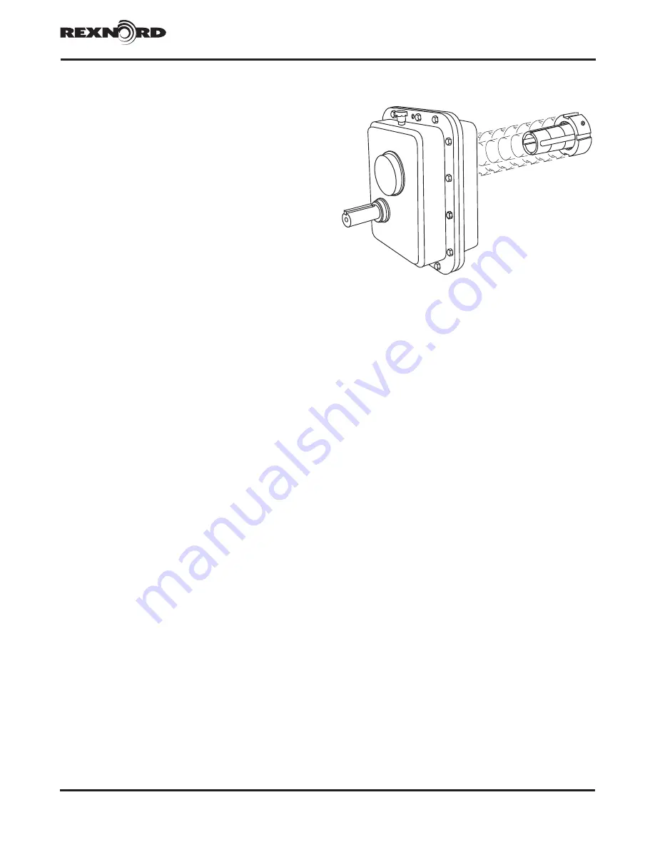
background image

Falk

®

 Quadrive

®

 Shaft Mounted Drives Model A • Owners Manual


Sizes 5107-5315 

(Page 1 of 52)

Rexnord (PN-2128394) 

378-200

3001 W. Canal St., Milwaukee, WI 53208-4200 USA


January 2019

Telephone: 

414-342-3131

 Fax: 

414-937-4359

  www.rexnord.com 

Supersedes 04-17

TABLE OF CONTENTS

Introduction 2
Drive Identification 

3

SECTION I — DRIVE INSTALLATION

Outfitting 4
Installation 7
Lubrication 9
Start-up 9

SECTION II


— DRIVE SERVICE & REPAIR

Preventive Maintenance                                   10
Oil Changes                                                                                              10
Stored & Inactive Drives                                   10
Repair & Replacement                                                                         10
Drive Disassembly                                         12
Identifying & Ordering Parts                               14
Recommended Spare Parts                               14
Parts List of  Falk Part Numbers                           16
Bearing Cross Reference Numbers                       17
Seal Cross Reference Numbers                           17

SECTION III — DRIVE REASSEMBLY

Drive Reassembly                                         18

APPENDICES

Appendix A:  Lubrication Recommendations             23
Appendix B:  Backstop Installation                                                32
Appendix C:  TA Removal Tool                             34
Appendix D:  Motor Mount Installation                     36
Appendix E:  Vertical Standpipe Installation                             38
Appendix F:  Modifications for Non-Standard  


Mounting Positions                                                    40

Appendix G: Retaining Rings for Bushing Nuts and 


Thrust Plates, Tooth Combinations for 


Vibration Analysis & JSC Lip Seal 

 Accessory                                   42
Appendix H:  Drive Shaft Recommendations for  


Tapered Drive Shafts                        43

Appendix J:  Drive Shaft Recommendations Using  


TA Taper Bushing                            41

Appendix K:  Drive Shaft Recommendations Using 


(TCB) Kit                                     46

Appendix L:  V-Belt Guard Installation                                         48
Appendix M: Electric Fan Installation                     51
Appendix N: Reliability Package                                                     52

Summary of Contents for Falk Quadrive A

Page 1: ... Bearing Cross Reference Numbers 17 Seal Cross Reference Numbers 17 SECTION III DRIVE REASSEMBLY Drive Reassembly 18 APPENDICES Appendix A Lubrication Recommendations 23 Appendix B Backstop Installation 32 Appendix C TA Removal Tool 34 Appendix D Motor Mount Installation 36 Appendix E Vertical Standpipe Installation 38 Appendix F Modifications for Non Standard Mounting Positions 40 Appendix G Reta...

Page 2: ...the Company as a condition of operation WARNING Consult applicable local and national safety codes for proper guarding of rotating members Lock out power source and remove all external loads from drive before servicing drive or accessories CAUTION Do not weld the drive housing or accessories without prior approval from Rexnord Geared Products Welding on the drive may cause distortion of the housin...

Page 3: ...ans 5307 5315 only Vertical Standpipe NOTE Use a TA Taper bushing when mounting these drives on a straight driven shaft hollow shaft is taper bored Trough Ends Thrust Plate Kits V Belt Guards TA Removal Tool J is the basic drive identification It can be outfitted for use as a shaft mounted drive JR a flange mounted drive JF or a screw conveyor drive JSC as illustrated below These unique identifier...

Page 4: ...IGHEST INPUT SIDE PLUG 10 MAX 5 MAX 30 UP 20 FOR 5315 5 DOWN INCLINE ROTATION 5 MAX 10 MAX 5107 5115 5203 THRU 5315 0 Incline down on drives with backstop in 9 or 12 o clock mounting position HORIZONTAL DRIVES Figure 1 VERTICAL DRIVES ANGULAR LIMITS FOR HORIZONTAL MOUNTING ALL CLOCK POSITIONS 5107 5115 5203 THRU 5315 HOUSING FLANGE FASTENERS ANCHOR BRACKET TORQUE ARM FASTENER ALTERNATE LOCATION PR...

Page 5: ...shing may have to be pried open slightly Rotate the shaft so the external keyway in the bushing is at the 12 o clock position Then insert the drive key furnished with the bushing into the keyway Proceed to Step 7 4 JSC NOTE See Appendix K for non tapered drive shafts Remove the hollow shaft cover from the input side of the hollow shaft bore and save Separate contents from the drive shaft kit Insta...

Page 6: ...aft with masking tape or lightweight Kraft paper to protect against damaging the seal lips Coat the seal lips and straight portion of the drive shaft with bearing grease Line up the keyway in the drive shaft with the hollow shaft keyway and insert the drive shaft into the seal housing Remove the protective wrap and install the drive shaft key Insert the drive shaft into the hollow shaft The seal h...

Page 7: ...ING AROUND SEAL HOUSING AND INPUT SHAFT SLING FROM EYEBOLTS TABLE 5 Flange Mounted Drive Foundation Fastener Size Tightening Torque Non Lubricated Fasteners DRIVE SIZE Fastener Size and Grade Torque lb ft Nm Min Fastener Engagement Into Drive Housing Inches mm 5107 500 13UNC GR 5 69 94 76 19 3 5115 625 11UNC GR 5 137 186 94 23 9 5203 750 10UNC GR 5 245 332 76 19 3 5207 875 9UNC GR 5 380 515 88 22 ...

Page 8: ...mpound MUST be applied to the threads of the TA bushing nut WARNING DO NOT apply anti seize or lubricant to bushing or shaft surfaces Use of anti seize may prevent secure connection of the drive to the shaft and cause the drive to move WARNING Overtightening can fail the internal retaining ring see Appendix G for listing of retaining rings a PREFERRED METHOD Use a spanner Table 6 chain or pipe wre...

Page 9: ... shows in the oil level hole Coat the plug threads with 3 Permatex or equivalent thread sealant before replacing 17 JR JF JSC Where applicable pump grease into the high speed shaft seal cover with a Hand Grease Gun Figure 14 until fresh grease flows out along the shaft Wipe off excess grease from the shaft DO NOT use grease where it could contaminate the product e g foods drugs etc START UP 18 JR ...

Page 10: ...ve space Rotate the shafts several times by hand Before operating drives which have been stored or inactive must be filled to the proper level with oil meeting the specifications given in this manual Refer to Manual 128 014 for Start up after Storage instructions c c Product of the Daubert Chemical Company Chicago Illinois Periodically inspect stored or inactive gear drives and add Nox Rust VCI 10...

Page 11: ...ay and insert a screwdriver or piece of key stock to prevent rotation of the plate After torquing the bolt as instructed strike the bolt sharply with a hammer and re torque the bolt if separation of the drive from the shaft did not occur Repeat this procedure re torquing the bolt after each blow until separation occurs CAUTION Failure to follow this procedure may result in the destruction of the t...

Page 12: ...rive seal into bore too deep or disassembly of drive may be required to extract seal b Wrap several turns of tape around the drill bit approximately 250 6 mm from the drill point to prevent the drill bit from entering too deeply into the housing and damaging the bearing Grease or magnetize the drill bit to help retain the chips Drill two 125 3 mm diameter holes in the seal case 180 apart Control t...

Page 13: ...s a jackbolt to separate input and output housing halves using the tapped hole on input housing flange provided for this purpose Carefully lift off output housing Ref 11 12 Remove the shaft assemblies J05 3A 4A J09 J14 or J25 1A 2A 4A from input housing Ref 10 13 Drive seals out from input and output housing bores if replacement is indicated Remove gasket material seal compound and any accumulated...

Page 14: ...and 2A2 for a 5107J25 would be ordered as follows Seal cover 4723094 Seal 2921419 Shim gasket kit 4729429 Shaft assembly with gear 4729373 Bearing 2926359 Bearing 2926359 4 Table 12 and 13 convert Falk part numbers to bearing and seal manufacturer s part numbers Tooth combinations are listed in Appendix G 5 Place your order with your local Rexnord distributor If you need to locate a distributor ph...

Page 15: ...3131 Fax 414 937 4359 www rexnord com Supersedes 04 17 TYPE J05 TYPE J09 J14 J25 4A5 4A2 4A3 4A1 4A4 2A1 2A5 2A4 2A2 2A6 2A3 1A4 1A2 1A1 1A5 1A3 3A2 3A1 3A4 3A3 4A5 4A2 4A3 4A4 4A1 27 16 23 17 23 5A ASSY 19 25 11 2A ASSY 3A ASSY 4A ASSY 29 30 10 25 13 19 15 22 24 31 20 29 5A5 5107J 5115J ONLY 4A ASSY 1 ASSY 5A2 5A1 5A6 23 5A4 6A1 6A4 5215 THRU 5315 6A3 6A ASSY 5115 J25 ONLY 5A3 Figure 19 ...

Page 16: ...19339 2918700 2919359 0921354 2919215 1A2 Bearing 2926357 2919340 2919340 0921521 2919360 2916263 0921851 1A3 Pinion Shaft w 1A5 Key 4729368 4729382 4729041 4729056 4729071 4729089 4729107 1A4 Gear 1242532 1242536 1242834 1242842 1242849 1242857 1242861 5A Backstop Ass y 0795654 0793995 0785596 0783905 0785610 0785529 0757183 Rotating Elements J14 1A Shaft Ass y W O 1A4 Gear 4729369 4729383 472903...

Page 17: ...320 0921521 19138 19283 B 0921727 68462 68712 0921778 JM822049 JM822010 0921793 HM803149 HM803110 0921850 JHM807045 HM807010 0921851 46176 46368 0921853 46162 46368 2905191 497 492A 2911822 34478 34300 2916263 418 414 2916288 3879 3820 2918700 350A 352 2918701 339 332 2919215 HM813841A HM813810 2919338 26112 26283 S 2919339 LM48548A LM48510 2919340 17098 17244 B 2919359 386A 382A 2919360 3379 3320...

Page 18: ...surface c Slide or press all ball bearings and bearing cones tight against the shoulder CAUTION Do not apply force to the bearing rollers or roller cage Apply force against the inner race only 2 ASSEMBLY OF TAPERED ROLLER BEARING CUPS a SIZE 5107 THRU 5315 Drive high speed bearing cup Ref 1A2 or 3A2 intermediate speed bearing cup Ref 2A2 and low speed bearing cup 4A2 squarely into their respective...

Page 19: ...cool before proceeding Apply oil to the cooled bearing rollers and gear teeth to lubricate and avoid scoring of the working surfaces 6 BEARING ADJUSTMENT a SIZES 5107 THRU 5315 Bearing adjustment is made by adjusting thickness of metal shims Ref 24 behind bearing cups in input housing Ref 10 NOTE The thickest shim should be located adjacent to the bearing cup The thinnest shims should be located i...

Page 20: ...input housing Reinstall dowels shims and output housing cover torque housing flange fasteners Ref 25 to value in Table 14 Proceed to Step 7 7 Lower low speed Ref 4A high speed Ref 1A or 3A and intermediate Ref 2A shaft assemblies into input housing Reinstall dowels and output housing and torque flange fasteners to value listed in Table 14 Recheck low speed shaft with dial indicator to ensure that ...

Page 21: ... using a TA tapered bushing do not install backstop at this time If not refer to Appendix B for installation instructions 8 SHAFT COVER INSTALLATION Assemble output side high speed shaft cover Ref 16 and gasket Ref 23 Table 16 Cross tighten fasteners to 3 5 lb ft 4 7 Nm torque 9 SEAL INSTALLATION Refer to Section II Step 7 Position input end low speed and high speed shaft covers Ref 13 15 respecti...

Page 22: ...ndix D Motor Mount Installation 36 Appendix E Vertical Standpipe Installation 38 Appendix F Modifications for Non Standard Mounting Positions 40 Appendix G Retaining Rings for Bushing Nuts and Thrust Plates Tooth Combinations for Vibration Analysis JSC Lip Seal Accessory 42 Appendix H Drive Shaft Recommendations for Tapered Drive Shafts 43 Appendix J Drive Shaft Recommendations Using TA Taper Bush...

Page 23: ...0 to 125 F 34 to 52 C Gear drives equipped with internal backstop can use GMax in ambient temperatures above 20 F 29 C WARNING GMax 6000 is not compatible with petroleum mineral oil or PAO synthetic lubricants and must not be topped off with either lubricant In addition petroleum mineral oils or PAO synthetic lubricants must not be used to top off systems containing GMax 6000 Do not use GMax 6000 ...

Page 24: ...ry analysis is recommended for optimum lubricant life and gear drive performance approaching that of extreme pressure EP lubricants end user should consult lubricant manufacturer supplier and Rexnord as necessary Typically EP lubricants in Tables 5B 6B contain these additives MICROPITTING RESISTANT LUBRICANTS TABLES 5C 6C Micropitting resistant lubricants are specially developed for surface harden...

Page 25: ...s TABLE 5B Petroleum Based EP Extreme Pressure Lubricants Maximum Operating Temperature of Lubricants 200 F 93 C ISO Viscosity Grade 220 320 AGMA Viscosity Grade 5 6 Viscosity cSt 40 C n 198 242 288 352 Viscosity SSU 100 F 918 1122 1335 1632 Manufacturer Lubricant Name Lubricant Name Castrol Industrial Lubricants Alpha SP 220 Alpha SP 320 Chevron Texaco Caltex Meropa 220 Meropa 320 Ultra Gear 220 ...

Page 26: ...astrol Isolube EP 68 Alphasyn EP 150 Alphasyn EP 220 Alphasyn EP 320 Castrol Isolube EP 150 Castrol Isolube EP 220 Castrol Isolube EP 320 Chevron Texaco Caltex Tegra Synthetic Gear Lubricant 150 Tegra Synthetic Gear Lubricant 220 Tegra Synthetic Gear Lubricant 320 Citgo Petroleum Corp CITGEAR Synthetic EP Gear 68 CITGEAR Synthetic EP Gear 150 CITGEAR Synthetic EP Gear 220 CITGEAR Synthetic EP Gear...

Page 27: ...ge the seals with one of the NLGI 2 grade greases listed in Table 7 Depending upon the degree of contamination it may be necessary to purge contaminated grease from seals more often at least every 3 to 6 months Slowly pump fresh bearing grease through the seal WITH HAND GREASE GUN until fresh grease flows out along the shaft Wipe off purged grease WARNING Greases in Table 7 contain harmful substan...

Page 28: ...ased lubricants See Table 10 for synthetic lubricants TABLE 9 Viscosity Grade Recommendations For Food Grade Petroleum Based Lubricants Ambient Temperature Range 30 to 90 F 1 to 32 C 70 to 125 F 21 to 52 C ISO Viscosity Grade 220 320 AGMA Viscosity Grade 5 6 c c Gear drives NOT equipped with internal backstop may widen the ambient temperature range to 18 to 125 F 28 to 52 C TABLE 10 Viscosity Grad...

Page 29: ...ating temperature of lubricants 200 F 93 C ISO Viscosity Grade 32 68 150 220 320 AGMA Viscosity Grade 0 2 4 5 6 Viscosity cSt 40 C 28 2 35 2 61 2 74 8 135 165 198 242 288 352 Viscosity SSU 100 F 134 164 284 347 626 765 918 1122 1335 1632 Manufacturer Lubricant Name Lubricant Name Lubricant Name Lubricant Name Lubricant Name ExxonMobil Mobil SHC Cibus 32 Mobil SHC Cibus 68 Mobil SHC Cibus 150 Mobil...

Page 30: ...luber Lubrication Klubersynth UH1 14 222 Lubriplate Lubriplate FGL 2 Total Lubricants USA Inc Nevastane HT AW 2 Petro Canada Purity FG Phillips 66 Conoco 76 Lubricants Kendall Food Machinery Grease 2 c c NSF National Sanitation Foundation H1 Registered Grease application or re lubrication should be done at temperatures above 20 F 7 C If grease must be applied at cooler temperatures consult lubrica...

Page 31: ...del A Appendix A Sizes 5107 5315 Page 31 of 52 Rexnord PN 2128394 378 200 3001 W Canal St Milwaukee WI 53208 4200 USA January 2019 Telephone 414 342 3131 Fax 414 937 4359 www rexnord com Supersedes 04 17 THIS PAGE LEFT INTENTIONALLY BLANK ...

Page 32: ...ions The backstop is designed to prevent reverse rotation five times or less in eight hours with one minute or more in overrunning direction between backstopping load applications If backstopping operations are more frequent or the time between operations is less than one minute the backstop is classified as an indexing device and must be referred to the Factory INSTALLATION Backstop Added to Exis...

Page 33: ... aligned with the housing backstop oil feed hole to provide proper lubrication to the backstop Install fasteners with lock washers and cross tighten to 8 lb ft 11 Nm torque Clean housing surface for rotation and WARNING labels Affix the rotation indicator label next to the high speed shaft extension to indicate the free direction of rotation Figure 4 Fill to oil level specified in Section I with o...

Page 34: ...d on the driven shaft b Remove belts from input shaft sheave c Remove the backstop if so equipped Refer to Section II Step 10 for backstop removal instructions CAUTION DO NOT disconnect the drive from its torque arm until the removal process is completed In addition the drive must be supported during removal process Use a sling around the motor mount or as recommended in Section I Step 7 Be sure t...

Page 35: ...ate freely for approximately 180 as it moves from the locked to the removal position Resistance will indicate that unseating is occurring Turn until the nut and bushing are completely free Now prepare the drive for lifting by disconnecting the torque arm at the drive end 6 ALTERNATE METHOD Torque may be applied to the sheave or sprocket mounted on the input shaft TOOL SIZES 5107 5115 5203 5207 LOW...

Page 36: ...MBLY The motor mount may be mounted on the high speed shaft end of FLANGE MOUNTED DRIVES JF also SCREW CONVEYOR DRIVES JSC if clearance over the trough end permits when increased motor mount clearance is required at the driven machine Consult Factory for SHAFT MOUNTED DRIVES JR GUARDS CAUTION Consult applicable local and national safety codes for proper guarding of rotating members Mounting slots ...

Page 37: ...eg Fastener Quantity Per Side A6 Shaft Centers Drive Size 5107 5115 5203 5207 5215 5307 5315 Compact 3 3 4 Short 3 3 4 4 4 6 Medium 3 3 3 3 3 5 Long 2 2 2 2 2 4 A3 A9 Shaft Centers Compact 3 3 3 Short 3 3 3 3 3 5 Medium 3 3 3 2 2 4 Long 2 2 2 3 RIGHT WRONG LEVEL GEAR DRIVE WALL SQUARE AND PARALLEL Figure 4 TABLE 2 Motor Mount Fasteners Torques lb ft Nm DRIVE SIZE Support Leg to Baseplate Support S...

Page 38: ...ich of the upper four side plug locations on the drive will provide the best location for the standpipe observing clearance required to remove dipstick Dimension D Table 1 Discard the air vent When the air vent location is not used for the standpipe relocate the pipe plug from the selected standpipe location to the air vent location Re coat pipe plug threads with Permatex 3 or equivalent sealant b...

Page 39: ...el A Owners Manual Sizes 5107 5315 Page 39 of 52 Rexnord PN 2128394 378 200 3001 W Canal St Milwaukee WI 53208 4200 USA January 2019 Telephone 414 342 3131 Fax 414 937 4359 www rexnord com Supersedes 04 17 THIS PAGE LEFT INTENTIONALLY BLANK ...

Page 40: ...e basic 3 6 9 12 o clock mounting positions are given in Section I Page 4 For higher limits follow the instructions at the left and the drawings below 6 o clock illustrated CODE B Bushing N Nipple C Cap P Pipe Plug E Street Elbow STD No Modifications L Oil Level HORIZONTAL DRIVE MODIFICATIONS 20 MAX DRIVE ROTATION 5 to 20 CW Rotation Sizes 5107 5115 10 to 20 CW Rotation Sizes 5203 thru 5315 5 to 2...

Page 41: ...Down 6 o clock H S S Up 6 o Clock H S S Down 9 o clock H S S Up 9 o Clock H S S Down 12 o Clock H S S Up 12 o Clock H S S Down 5107 THRU 5315 STD 5107 THRU 5315 STD 5107 THRU 5307 STD 5315 KIT 0786776 5107 THRU 5315 STD 5107 5 25 375 E P 5107 26 30 375 E C 375 X 1 00N KIT 0786775 5115 5 20 375 E C 375 X 1 00N 5115 21 30 375 E C 375 X 2 00N KIT 0786775 5203 5 30 375 E C 375 X 1 50N 5207 5 15 375 E ...

Page 42: ...25 47 14 68 Type J14 Tooth Combinations DRIVE SIZE Exact Ratio Input Output Pinion Ref 1A3 Gear Ref 1A4 Pinion Ref 2A3 Gear Ref 4A4 5107 14 43 19 54 13 66 5115 13 95 21 58 19 96 5203 14 45 20 57 14 71 5207 14 47 20 57 13 66 5215 13 60 21 58 13 64 5307 14 03 18 52 14 68 5315 13 91 22 63 14 68 Type J25 Tooth Combinations DRIVE SIZE Exact Ratio Input Output Pinion Ref 1A3 Gear Ref 1A4 Pinion Ref 2A3 ...

Page 43: ...438 4 25 5215 750 19 05 4 250 107 95 3 258 82 753 3 500 88 90 750 19 05 2 923 74 24 7 616 193 45 3 75 95 3 2 00 50 8 1 19 30 2 875 9 2 50 63 5 750 500 3 50 5307 875 22 23 5 875 149 22 3 878 98 501 4 100 104 14 875 22 22 3 413 86 69 8 008 203 40 4 46 113 3 2 04 51 8 1 27 32 2 1 000 8 2 75 69 8 875 625 5 00 5315 1 000 25 40 6 000 152 40 4 433 112 598 4 664 118 47 1 000 25 40 3 871 98 32 8 398 213 31...

Page 44: ...shing when the drive shaft is removed from the drive The threaded hole in the end of the drive shaft accepts the thrust plate fastener WARNING Lock out power source and remove all external loads from system before servicing drive or accessories INSTALLATION PROCEDURE With the drive shaft manufactured per the recommendations shown and the bushing selected for the proper shaft diameter remove and di...

Page 45: ... 57 15 1 735 1 725 0 068 0 072 RST 181 2 000 0 500 0 2500 4 000 101 60 0 500 13 2 00 50 8 5203 TP4203JF 0778775 5 310 134 87 5 625 142 88 1 634 41 5 1 921 48 8 3 500 88 90 2 1875 2 500 63 50 1 952 1 940 0 086 0 091 RSN 206 2 250 0 500 0 2500 4 625 117 48 0 625 11 2 00 50 8 5207 TP4207JF 0778776 5 890 149 61 6 250 158 75 1 557 39 6 1 885 47 9 4 000 101 60 2 4375 2 750 69 85 2 290 2 278 0 056 0 060 ...

Page 46: ...s follows 5107 5215JSC The seal housing may be assembled to the drive before or after the drive shaft is installed into the drive depending on the shaft extension diameter 5307 5315JSC The seal housing must be assembled over the drive shaft from the extension end of the shaft or the shaft shoulder must be fixed in position after the seal housing is assembled over the drive shaft see Figure 2 ALL J...

Page 47: ...ir O Lox RST 181 2 000 0 500 0 2500 4 000 101 60 0 500 13 2 00 50 8 TCB5203J 2 188 0766043 5 310 134 87 5 625 142 88 2 346 59 59 2 099 53 31 2 1875 2 625 66 68 1 952 1 940 0 086 0 091 Spir O Lox RSN 206 2 250 0 500 0 2500 4 625 117 48 0 625 11 2 00 50 8 TCB5207J 2 438 0766044 5 890 149 61 6 250 158 75 2 548 64 72 2 260 57 40 2 4375 3 000 76 20 2 290 2 278 0 056 0 060 Spir O Lox RS 236 2 500 0 625 ...

Page 48: ...er with belt no screws with screws with cover plate with pulleys CH_930001 WARNING CH_930001 WARNING 1 ASSEMBLE MOTOR MOUNT AND MOTOR TO DRIVE AS INSTRUCTED IN APPENDIX D 4 ASSEMBLE SLOT COVER S AS REQUIRED 2 ASSEMBLE BELTGUARD BACKPLATE WITH SPACERS TO DRIVE FRONT 5 MOUNT BELT DRIVE AS INSTRUCTED IN APPENDIX D 3 ASSEMBLE BELTGUARD BACKPLATE TO MOTOR PLATE 6 MOUNT COVER AND APPLY WARNING LABEL no ...

Page 49: ...late with sheaves with belt guard cover CH_930001 WARNING er and plate with sheaves with belt guard cover with belt guard back with hardware with fan with fan cover and plate ith hardware with fan with fan cover and plate with sheaves with belt guard cover CH_930001 WARNING h belt guard back with hardware with fan with fan cover and plate with sheaves with belt guard cover CH_930001 WARNING 1 ASSE...

Page 50: ... screws through fan mounting holes in shroud with threaded portion of cap screw away from drive Secure cap screws to shroud with flat washers and hex nut See Figure 2 3 Mount shroud to drive using spacers and hardware See Figure 1 4 Assemble V belt guard bracket 5 Position the electric fan panel on the remaining threaded portion of the cap screws and secure it to the shroud with four locknuts See ...

Page 51: ...hat the installed fittings are oil tight The Reliability Package can be assembled by following the steps outlined below 1 Pipe Plugs Remove the two 2 1 25 NPT pipe plugs from locations 1 2 of the gearbox as shown in Figure 2 LOCATION 2 ELBOW SUBASSEMBLY LOCATION 1 SIGHT GLASS SUBASSEMBLY LOCATION 3 OIL FILL Figure 2 Pipe Plug Locations PIPE WRENCH PIPE NIPPLE 2 Sight Glass Subassembly Prepare the ...

Page 52: ...d to be used when the gearbox is not running in the static condition Therefore the sight glass contains a label that indicates a static oil level oil levels tend to fluctuate based on oil churning and are dependent on speed and direction of rotation for continuous direction and continuous speed applications it is recommended that the oil level sight glass be marked once steady state operating cond...

Reviews: