Peiying PY0105, Owner'S Manual
The Peiying PY0105 Owner's Manual is available for free download on our website. This comprehensive manual provides detailed instructions on how to maximize the features and functionalities of the PY0105 product. Enhance your user experience with this convenient manual, exclusively available at manualshive.com.
Share
Download


Reviews:
No comments
Related manuals for PY0105
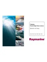
T300
Brand: Raymarine Pages: 38

53157
Brand: Hama Pages: 60

PL1148
Brand: safer guard Pages: 7

CAMEDIA D-460 Zoom
Brand: Olympus Pages: 2

GDVR189
Brand: Gator Pages: 13
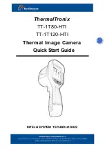
ThermalTronix TT-1T80-HTI
Brand: Intellisystem Pages: 5

ViviCam E128
Brand: Vivitar Pages: 68

999-50707-001G
Brand: VADDIO Pages: 69

ioi HD CF-5212
Brand: FLIR Pages: 2

ACM-8511
Brand: ACTi Pages: 12

XCM16K80SAT8
Brand: NED Pages: 69

180-View 180NT-P-CM
Brand: Tamron Pages: 39

XV20DVR
Brand: Xview Pages: 16

SW005
Brand: Silent Witness Pages: 17

LIFE E42001
Brand: Medion Pages: 12

KE115 - Zoom 35 Mm Camera
Brand: Kodak Pages: 102

Lumix DMC-FX700P
Brand: Panasonic Pages: 68

Lumix DMC-FX80PU
Brand: Panasonic Pages: 81


