background image

Before attempting to connect or operate this product,

please read these instructions carefully and save this manual for future use.
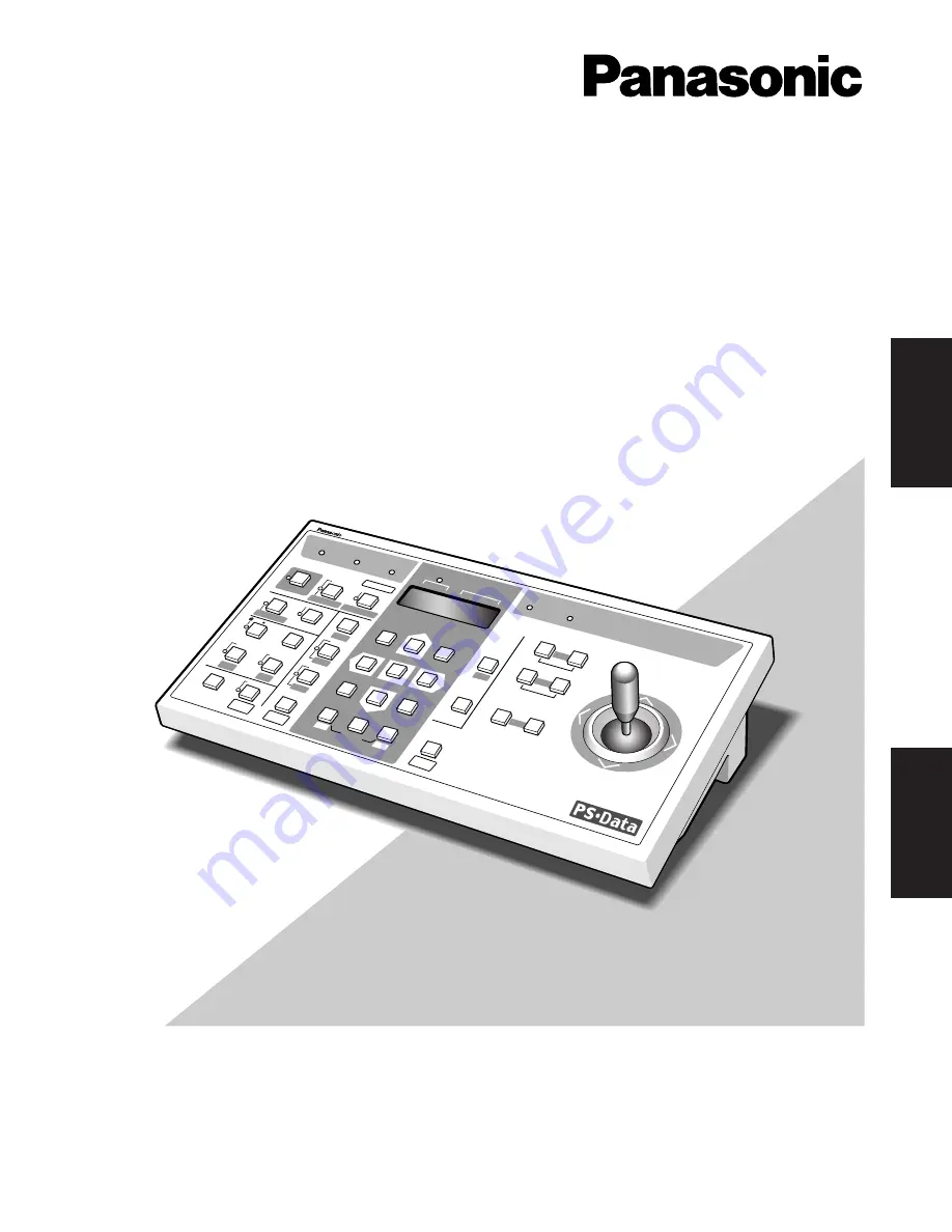
Model No.

WV-CU360C

System Controller

Operating Instructions

System Controller WV-CU 

360

C

OPER

ATE

LOGIN

ALAR

M

MONIT

OR

UNIT

CAMER

A

BUSY

PROHIBITE

D

SHIFT

FUNC

TION

CAM

 FUNC

TION

PRO

GRAM

ALM

 RESE

T

VCR     C

AM

MULTI SCREEN SELECT

STILL

SEQ PAUSE

SEQUENCE

SLOW

PATROL

LEARN

PROGRAM

PRESET

PATROL

STOP

ESC

SET

LOGOUT

MON

CAM

PATROL PLAY

+

AUX  1

WIPER

HOME

/PRESE

T

AUX  2

DEF

UNIT B

ZOOM

WIDE

TELE

DOWN

L

R

UP

EL-Z

OOM

ALM RECALL

ALM

 SUSP

END

AUTO

FOCU

S

FAR

NEAR

UNIT A

 UNIT

B/W

SETUP

CAM SETUP

CLOSE

IRIS

OPEN

IRIS RESET

AUTO FOCUS

8

9

7

0

4

5

6

2

3

1

ENGLISH

FRANÇAIS

Summary of Contents for WVCU360C - SYSTEM CONTROLLER

Page 1: ...MONITOR UNIT CAMERA BUSY PROHIBITED SHIFT FUNCTION CAM FUNCTION PROGRAM ALM RESET VCR CAM MULTI SCREEN SELECT STILL SEQ PAUSE SEQUENCE SLOW PATROL LEARN PROGRAM PRESET PATROL STOP ESC SET LOGOUT MON CAM PATROL PLAY AUX 1 WIPER HOME PRESET AUX 2 DEF UNIT B ZOOM WIDE TELE DOWN L R UP EL ZOOM ALM RECALL ALM SUSPEND AUTO FOCUS FAR NEAR UNIT A UNIT B W SETUP CAM SETUP CLOSE IRIS OPEN IRIS RESET AUTO FO...

Page 2: ...VICING TO QUALIFIED SERVICE PERSONNEL CAUTION RISK OF ELECTRIC SHOCK DO NOT OPEN SA 1965 SA 1966 NOTE This equipment has been tested and found to comply with the limits for a Class A digital device pursuant to Part 15 of the FCC Rules These limits are designed to provide reasonable protection against harmful interference when the equipment is operated in a commercial environment This equipment gen...

Page 3: ... outlet consult an electrician for replacement of the obsolete outlet 10 Protect the power cord from being walked on or pinched particularly at plugs convenience receptacles and the points where they exit from the apparatus 11 Only use attachments accessories specified by the manufacturer 12 Use only with the cart stand tripod bracket or table specified by the manufacturer or sold with the apparat...

Page 4: ...tions 43 DIP Switch Setting 44 Controller Number Setting 45 SETUP PROCEDURES For WJ FS616C 46 Prior to Setup 46 Buttons and Controls used in Setup 46 Controller Setup 47 OPERATING PROCEDURES For WJ FS616C 49 Camera Selection 49 Camera Control 49 Alarm Operation 50 VTR VCR Control 50 Camera Setup 51 Chapter 3 For WJ SX350 Matrix Switcher System 53 MAJOR OPERATING CONTROLS THEIR FUNCTIONS 54 Front V...

Page 5: ...yout Electronic Zoom Sequence System Unit Selection PRECAUTIONS Refer all work related to the installation of this product to qualified service personnel or system installers Do not attempt to disassemble the appliance To prevent electric shock do not remove screws or covers There are no user serviceable parts inside Contact qualified service personnel for maintenance Handle the appliance with car...

Page 6: ...ches MODE The DIP switches are used to set communication para meters for the System Controller e Data Ports DATA These ports are used to exchange control data with the connected system units via the supplied RS 485 cable r DC 9 V Input Jack DC 9V IN Jack for the DC plug of the supplied AC adapter t Clamp The clamp fastens the power cord to the AC adapter y AC Adapter Caution Use only the supplied ...

Page 7: ...REV SEQ SEQ TOUR GROUP ALARM DISARM ACK RESET GROUP PRESET NEXT LOG OUT PAUSE STOP F1 F2 MONITOR CAM FUNC LOCK OSD SERVICE CAMERA ENTER CLEAR ESC CALL PRESET PROGRAM PRESET SHIFT DEF OFF DEF ON AUX2 OFF AUX2 ON AUX1 OFF AUX1 ON CAM ID OPE ID S CTL ID OSD CAM MENU OFF CAM MENU ON ALL RESET MDN STATUS WIPER GEN ALL EXIT BLK VLD H ALM H VLD S SYS S ALM S AUTO PAN UP L R DOWN For Matrix Switcher Syste...

Page 8: ... OFF ON 0 9 8 7 6 5 4 3 2 1 CONTROLLER No System Controller No SW MODE DIP SW PS Data MODE 1 2 3 4 5 6 7 8 OFF ON WJ FS616C MODE 1 2 3 4 5 6 7 8 OFF ON CONTROLLER No WJ FS616 MODE 1 2 3 4 5 6 7 8 OFF ON CONTROLLER No WJ SX350 Ver 6 00 or later MODE 1 2 3 4 5 6 7 8 OFF ON CONTROLLER No WJ SX350 Ver 1 xx MODE 1 2 3 4 5 6 7 8 OFF ON CONTROLLER No System 850 WJ SX850 0 9 8 7 6 5 4 3 2 1 CONTROLLER No ...

Page 9: ...9 Panasonic Security Data PS Data Systems ...

Page 10: ...pera tor or when a higher priority operator selects the cam era or system unit you are currently operating Operations from the System Controller are disabled until this indicator goes off u Prohibited indicator PROHIBITED Lights up when an attempt is made to access a function that is prohibited to the operator level i Joystick Controller UP DOWN L R Used to manually operate the pan tilt head or mo...

Page 11: ...ing this button together with the MON ESC button for approximately 2 seconds will log out from the sys tem 7 Monitor Escape button MON ESC MON Used for monitor selection and confirmation To select a monitor enter the desired monitor number with the numeric buttons and then press this but ton The selected monitor number appears on the LED display To confirm a monitor number simply press this but to...

Page 12: ...ture of a camera and the playback picture of a recording device The LED next to the but ton is lit while VCR is selected 9 Electronic Zoom Increment button EL ZOOM Zooms the camera picture or VCR playback picture dis played on the multiscreen monitor Pressing this button in the shift mode will move the camera sequence one step forward from the step previ ously paused while a system unit provided w...

Page 13: ...ra No 3 Camera No 4 Camera No 5 Camera No 6 Camera No 7 Camera No 8 VS VD INPUT Unit Address 1 Unit Address 2 WJ MP204C WJ MP204C WJ FS316 WJ HD100 Unit Address 3 Unit Address 4 Video Signal 6 conductor Modular Cable supplied Termination ON MODE VS VD OUTPUT 4 Line Monitor No 1 Monitor No 2 Panasonic Security Data mode Termination OFF Panasonic Security Data mode 4 Line MODE VD OUT RS 485 Signal P...

Page 14: ...ultiplex Unit WJ MP204 Data Multiplex Unit WJ MP204 WJ MP204C WV CU360C 4 cameras can be connected to one Data Multiplex Unit UP L R DOWN UP L R DOWN Up to 4 Data Multiplex Units Up to 4 System Controllers Channel 1 Channel 2 Channel 4 Channel 13 Channel 14 Channel 16 Unit address 1 Controller No 1 Controller No 2 Controller No 4 Unit address 2 Unit address 4 See page 16 for MODE switch and CONTRO...

Page 15: ...stem Unit Version System Unit Version System Unit Version Operator Fixed to OFF Fixed to OFF Off Fixed to OFF Fixed to OFF Fixed to OFF Fixed to OFF Administrator Not used Not used On Not used Not used Not used 1 Remove the DC plug from the rear of the controller 2 Set the switch referring to the table 3 Connect the DC plug to the controller Notes Bits 1 4 are reserved Bit 5 opens or terminates th...

Page 16: ...Data system 1 Remove the DC plug from the rear of the controller 2 Use a screw driver to rotate the switch so that the arrow comes to the number you wish 3 Connect the DC plug to the controller Notes Set the switch to 1 when a single controller is used in the system Specify a unique number for each controller when con necting multiple controllers in the system One con troller within the multiple c...

Page 17: ...ve bit 6 of the MODE switch on the rear to OFF operator position 2 Supply power to the controller Buttons and Controls used for Setup The following buttons and joystick operations are used in the setup operation There are three ways to select a para meter but the following pages only describe the selection by use of the joystick Instead of operating the joystick you can enter the number enclosed i...

Page 18: ...l Display Authorization Baud Rate bps Press twice Parity Check Wait Time ms Unit Assignment to Button A Unit Assignment to Button B Administrator Password User Authorization Camera Cleaning Unit Connection Test CAM SET CAM SET MON ESC CAM SET LED prompts you to enter a pass word Enter a 5 digit password press 12345 1 2 400 2 4 800 3 9 600 4 19 200 1 None 2 Even 1 Off 2 100 3 200 4 400 5 1 000 Leav...

Page 19: ... 9 600 9 600 bps 4 19 200 19 200 bps Note Selecting a slower rate e g 2 400 bps will delay the response time e g the time until an acti vated alarm is reset 3 Press the CAM SET button to validate the selection 4 Press the ESC button to go back to the previous menu Parity In this menu the parity check mode is selected 1 Display PrtY and press the CAM SET button twice 2 Select a parameter with the j...

Page 20: ...the selection Repeat above the steps 2 to 5 as needed 6 Press the ESC button to go back to the previous menu Unit B button Assignment The UNIT B button is set up in the same way as the UNIT A button for use in normal operation Refer to the above description for Unit A button Assignment User Password In this menu a 5 digit password for user authorization is registered 1 Display UsrP and press the C...

Page 21: ...cam era cleaned is displayed without animation 4 Press the ESC button to go back to the previous menu Unit Connection Test This menu is for specifying the order in which data commu nication between system units is tested prior to operating the system as a whole 1 Display UtESt and press the CAM SET button The LED displays 01 on or 01 oF 2 Enter the 2 digit unit number you wish to start with 3 Pres...

Page 22: ...ONITOR SELECTION LOG OUT SYSTEM OPERATION Alarm Reset Alarm Suspend Alarm Suspend Cancel SYSTEM UNIT OPERATION System Unit Setup System Function Alarm Recall CAMERA OPERATION Camera Setup Pan Tilt Slow Iris Focus Zoom Preset Position Home Position Switching of Color Black White Auto Panning Camera Patrol Camera Patrol Stop Camera Patrol Learn Camera Function Wiper Defroster Auxiliary Control 1 2 C...

Page 23: ...al factory setting is 12345 5 Press the CAM SET button 6 If password entry for user authorization has been suc cessful the LOGIN indicator lights up The unit assigned to the UNIT A UNIT button as number 1 is selected automatically If password entry has failed Error appears on the dis play The display returns to LogIn Log Out 1 Press the MON ESC and CAM SET buttons for about 2 seconds simultaneousl...

Page 24: ...nit Number 1 Enter a unit number 01 99 with the numeric buttons 2 Press the SHIFT button to turn the shift indicator on then press the UNIT A UNIT button The selected unit number appears in the unit section of the LED display The selected camera number appears in the camera section of the LED display Notes To confirm the selected unit number when the moni tor number appears in the unit section of ...

Page 25: ...elected system unit is not compatible with the monitor selection For further information refer to the Operating Inst ructions for the system unit concerned MON CAM LOGOUT ESC SET MON ESC Camera Selection One of the cameras connected to the system unit is select ed 1 Select a system unit connected to the camera whose picture you wish to view 2 Enter a camera number using the numeric buttons The ent...

Page 26: ... Some of the descriptions may not be applicable if they refer to devices not equipped in your sys tem The operating procedures on the following pages assume that you have selected a system unit and a monitor Pan Tilt Control Proceed as follows to control a combination camera or an ordinary camera mounted on a pan tilt head 1 Move the pan tilt head in the desired direction with the joystick control...

Page 27: ...RT Begin 1 0 0 CAM FUNC Memorize PRESET From 1 to 64 Position 1 1 0 1 CAM FUNC Position 10 1 1 0 CAM FUNC Position 64 1 6 4 CAM FUNC PATROL PLAY 1 6 5 CAM FUNC STOP 1 6 6 CAM FUNC LEARN Start 1 6 7 CAM FUNC IRIS Open 1 6 9 CAM FUNC Close 1 7 0 CAM FUNC EL SHUTTER On 1 7 1 CAM FUNC Off 1 7 2 CAM FUNC Speed Up 1 7 3 CAM FUNC Speed Down 1 7 4 CAM FUNC AGC On 1 7 5 CAM FUNC Off 1 7 6 CAM FUNC SENS UP ...

Page 28: ...e the auxiliary function for the selected camera The respective indicator next to the button is lit while it is in operation Note Auxiliary control may be ignored while zooming focusing or panning tilting is in operation Data Multiplex Unit Control When more than one Data Multiplex Unit are connected with the controller as shown in System Connection Example 2 on page 14 you can select a camera dir...

Page 29: ...t a camera number using the numeric buttons then press the STILL button The selected camera picture freezes on the multiscreen while the STILL indicator is lit 2 Press the STILL button to cancel still display mode 8 All cameras still 1 Enter 0 with the numeric buttons then press the STILL button All camera pictures freeze on the mul tiscreen while the STILL indicator is lit 2 Press the STILL butto...

Page 30: ...Multiplexer Set PLAYBACK AUTO to OFF in the setup when you wish manual operations as described above Sequence Control A preset sequence is displayed on the selected spot or multiscreen monitor The paused picture can be moved by one step to the previous or next frame 1 Press the SEQUENCE button The sequence is dis played on the monitor while the SEQUENCE indicator is lit 2 To pause the sequence pre...

Page 31: ...ock is released automatical ly by opening the setup menu Operate LCD Button STOP SETUP ESC Hold down 2 seconds STEP PUSH PAUSE SET PUSH PAUSE SET STOP SETUP ESC STOP PLAY CAM MON ESC SET REW FF SETUP FUNCTION Hold down 2 seconds DOWN L R UP L R DOWN L R UP DOWN L R MON ESC ALM RESET ALM RECALL SHIFT Recording REC SETUP FUNCTION SHIFT Stop Stop Playback Stop Recording STOP SETUP ESC STOP STOP SETUP...

Page 32: ...Step Playback FWD Step Playback REW Pause Playback Recording Stop Stop Playback Stop Recording Alarm Search OFF Alarm Search ON Button Lock OFF Button Lock ON Daylight Savings ON OFF Timer Mode Selection Record List Display ON OFF Record Search Window ON Equal to REC button For both Manual Recording and Playback Exclusive use to stop playback Exclusive use to stop recording Internal External Off I...

Page 33: ...arch in Window Increment Parameter in Window Decrement Parameter in Window Search Window Display Selection Speed change 1 2 1 2 5 Speed change 1 2 1 2 5 Record List Record List Record List Record List Record List Record List Alarm Log Alarm Log Alarm Log Alarm Log Alarm Log Time Date Alarm CH OFF SHIFT SETUP FUNCTION SHIFT SETUP FUNCTION SHIFT ALM RESET ALM RECALL SHIFT SETUP FUNCTION SHIFT SETUP ...

Page 34: ...t to be disturbed by alarm input as for example during setup operations 1 Press the ALM SUSPEND button The ALM SUSPEND indicator lights up Alarm input is ignored while the indicator is lit ALM RESET ALM RECALL ALM SUSPEND 2 To cancel alarm suspension press the ALM SUSPEND button again Note The alarm suspension is applied to all system units not to a selected one Alarm Recall The alarm event log is...

Page 35: ... setup function is disabled Keys used for system unit setup Example of Setup Menu for WJ MP204C WJ MP204C SETUP MENU x xx COMMUNICATION SYSTEM Camera Setup 1 Select the desired camera 2 Press the CAM SETUP CAM FUNCTION button for 2 seconds or more to access the Camera Setup menu The CAM SETUP indicator lights up 3 Move the cursor with the numeric buttons 2 Up or 8 Down then select a parameter with...

Page 36: ...ION button LEARNING disappears from the monitor 7 Move the cursor to SPECIAL on the Setup menu and press numeric buttons 4 and 6 simultaneously for 2 seconds or more to display the special menu 8 Move the cursor to CAMERA RESET on the Setup menu and press buttons 4 5 and 6 simultaneously to reset all the functions to the defaults The menu to reset the camera functions differs depend ing on the cam...

Page 37: ...tons Iris Open Close Focus Far Near Zoom Tele Wide Note The memorized parameters may differ somewhat depending on the camera type Refer to the manual included with the camera 3 Type a number with the numeric buttons for the pre set position The typed number appears in the CAMERA section of the LED display 4 Press the HOME PRESET PROGRAM PRESET button while holding down the PROGRAM CAM SETUP CAM FU...

Page 38: ...39 For WJ FS616C Multiplexer System ...

Page 39: ...king changes to steady light when the alarm is automatically reset To turn the indicator off press the ALM RESET button r LED Display UNIT CAMERA LED display allowing you to confirm the number of the system unit and camera in operation The CAMERA section will display when operating in multiscreen or sequence mode t Iris buttons IRIS CLOSE OPEN Close or open the lens iris of cameras equipped with t...

Page 40: ...e spot monitor is select ed 8 Alarm Reset button ALM RESET Cancels an active alarm Pressing this button while the alarm function is activat ed will reset an alarm of the currently selected unit and return the system to the condition before the alarm function was activated Pressing it in combination with the ALT button will reset all alarms 9 Sequence button SEQUENCE Activates the sequence mode In ...

Page 41: ...r The indicator lights up when the still mode is selected 7 Camera Set buttons CAMERA SET ON OFF Open or close the camera setup menu on the monitor screen ON Opens the selected camera setup menu on the monitor if applicable The indicator lights up when the camera setup menu is displayed OFF Closes the camera setup menu 8 Set Up button SET UP ON OFF Opens or closes the WJ FS616 FS616C setup menu on...

Page 42: ... 10 14 1 5 9 13 PUSH OPEN 16 POWER LOCK ON OFF ALARM MULTI SCREEN MULTISCREEN SELECT RESET SPOT SEQUENCE VCR CAM CAMERA PRESET POSITION Video Data RS 485 Video Multiplexer WJ FS616C Time Lapse VCR Personal Computer Software System Controller WV CU360C Spot Monitor Live 1 16ch Multiscreen Monitor Live 1 16ch Playback 1 16ch RS 232C Wired Alarm Sensor AUX Alarm System Controller OPERATE LOCK ALARM S...

Page 43: ...troller WV CU360C DATA RS 485 Cable Termination ON Termination ON TERM OFF IN OUT ON DATA Video Multiplexer WJ FS616C DC 9V IN DATA MODE CONTROLLER No 0 9 8 7 6 5 4 3 2 1 SW position OFF Not used On Administrator Not used Not used Function ON Bit 1 Bit 2 Bit 3 Bit 4 Bit 5 Bit 6 Bit 7 Bit 8 Unit Version Unit Version Unit Version Reserved Line termination Operation mode Reserved Data transmission Se...

Page 44: ...ens or terminates the communication chain The switch should be set to OFF when the controller is locat ed in an intermediate position of the chain Bit 6 specifies either Operator or Administrator as the operation mode Set to Administrator when setting up the controller Bits 4 7 and 8 are reserved 3 Set the CONTROLLER NO switch to 1 4 Connect the DC plug to the controller Unit Version The unit ID i...

Page 45: ... LCD displays SEtUP The controller is ready to enter the setup mode When setup is completed restore the switch to its original position 1 With the power turned off move bit 6 of the MODE switch on the rear to OFF operator position 2 Supply power to the controller Buttons and Controls used for Setup The following buttons and joystick operations are used for setup 0 9 Numeric buttons To select a par...

Page 46: ... 9 600 bps 1 2 400 2 400 bps 2 4 800 4 800 bps 3 9 600 9 600 bps 4 19 200 19 200 bps Note Selecting a slower rate e g 2 400 bps will delay the response time e g the time until an activated alarm is reset 3 Press the CAM SET button to validate the selection 4 Press the ESC button to go back to the previous menu Parity In this menu the parity check mode is selected 1 Display PrtY and press the CAM S...

Page 47: ...e data communications will not function To confirm the WJ FS616 FS616C setup open the COM PORT SETUP window to check the DATA port column parameters Refer to Multiplexer Setup for operation COM PORT SETUP RS 232C DATA RS 485 DELAY OFF OFF OFF BAUD RATE 9600 9600 19200 WAIT TIME OFF OFF OFF DATA BIT 7 8 8 PARITY ODD NONE NONE STOP BIT 1 1 1 XON XOFF OFF OFF FULL HALF FULL ...

Page 48: ...ra Camera Control Cameras and their peripherals are controlled from the WV CU360C as follows Some of the descriptions may not be applicable if they refer to devices not equipped in your sys tem Pan Tilt Control Proceed as follows to control an ordinary camera mounted on a pan tilt head or a combination camera in manual or automatic panning mode 1 Move the pan tilt head in the desired direction wit...

Page 49: ...eset all alarms issued by the multiplexers connect ed in a daisy chain press the ALT button then press the ALM RESET buttons Alarm Suspension 1 Press the ALM SUSPEND button for more than 2 sec onds to suspend the alarm The ALM SUSPEND indi cator lights up 2 Press the ALM RESET button to reset alarm suspen sion The ALM SUSPEND indicator goes off VTR VCR Control You can operate a VTR VCR connected t...

Page 50: ... SEQUENCE button to enter the SPECIAL menu 6 Press the VTR CAM button to reset all functions to the defaults or press the SEQUENCE button to reset a selected function 7 Press the CAMERA SET OFF button to close the cam era setup menu Shortcut for Preset Position Setup A shortcut can be created for setting a camera position without going through the whole presetting process Shortcuts are applicable ...

Page 51: ...53 For WJ SX350 Matrix Switcher System ...

Page 52: ...successfully finished e Alarm indicator ALARM Blinks when an alarm condition exists It changes to steady light when the alarm is reset auto matically To turn off the indicator press the ACK RESET or ALL RESET button r LED Display MONITOR CAMERA Displays the number of monitors and cameras currently controlled t Busy indicator BUSY Blinks or lights up when you attempt to control a certain monitor or...

Page 53: ...ition by a serial number assigned indepen dently of the camera number Specify a number then press ALT and finally this button 4 Camera Set button CAM SET CAM Used for camera selection To select a camera enter the desired camera number with the numeric buttons and then press this button SET Executes the currently highlighted setting in the setup menu of the Matrix Switcher and opens a submenu 5 Num...

Page 54: ...y pressing the PAUSE button Also when the selected monitor is in the spot mode pressing this button will replace the currently selected camera with the next higher number cam era 6 Alarm Recall button RECALL Recalls the Alarm Log record of activated alarms Select the desired monitor to display the alarm records then press this button to toggle the display of alarm records On and Off on the selecte...

Page 55: ...UP DOWN ZOOM MATRIX SWITCHER WJ SX350 CAMERA SITE CONTROL Video Data RS 485 Up to 32 Cameras 32 Alarm Input System Controller Max 4 Units Video Monitor Max 8 Outputs Time Lapse VCR Max 8 Control Outputs Matrix Switcher WJ SX350 L CLOSE OPEN IRIS R UP DOWN NEAR FAR FOCUS BUSY TELE WIDE ZOOM 0 9 8 7 6 5 4 3 2 1 ALARM MONITOR CAMERA LOCK POWER PROHIBITED CAMERA SITE CONTROL L CLOSE OPEN IRIS R UP DOW...

Page 56: ...1 ALARM MONITOR CAMERA LOCK POWER PROHIBITED CAMERA SITE CONTROL L CLOSE OPEN IRIS R UP DOWN NEAR FAR FOCUS BUSY TELE WIDE ZOOM 0 9 8 7 6 5 4 3 2 1 ALARM MONITOR CAMERA LOCK POWER PROHIBITED CAMERA SITE CONTROL L CLOSE OPEN IRIS R UP DOWN NEAR FAR FOCUS BUSY TELE WIDE ZOOM 0 9 8 7 6 5 4 3 2 1 ALARM MONITOR CAMERA LOCK POWER PROHIBITED CAMERA SITE CONTROL L CLOSE OPEN IRIS R UP DOWN NEAR FAR FOCUS ...

Page 57: ... should be set to ON Bit 3 should be set to ON S E T U P M E N U 6 xx 1 xx P R O G R A M O P E R A T O R S Y S T E M C A M D A T A L O A D C A M E R A T I T L E C A M P O S I M A P F U N C T I O N K E Y MODE 1 2 3 4 5 6 7 8 OFF ON For version 1 xx set the switches as shown below Bit 1 should be set to OFF Bit 2 should be set to ON Bit 3 should be set to OFF Bits 4 through 8 are not version related...

Page 58: ... MODE switch on the rear to OFF operator position 2 Supply power to the controller DC 9V IN Buttons and Controls used for Setup The following buttons and joystick operations are used for setup 0 9 Numeric buttons To select a parameter CAM SET button To execute modes and parameters To enter a submenu MON ESC button To return to the previous menu CAM SET DOWN L R UP L R UP DOWN R UP DOWN L R Up To s...

Page 59: ...400 bps will delay the response time e g the time until an acti vated alarm is reset 3 Press the CAM SET button to validate the selection 4 Press the MON ESC button to return to the SPEED menu Parity The parity check mode is selected in this menu 1 Display PrtY and press the CAM SET button twice 2 Select a parameter with the joystick The default setting is None n None E Even parity 3 Press the CAM...

Page 60: ...ed another attempt can be made when the PROHIBITED indicator goes off after 2 seconds Logout 1 Type 00 using the numeric button then press the FUNCTION button The LOGIN indicator turns off Lens Control Auto Focus Operation The following function requires the use of a camera with auto focus capability such as the Panasonic WV CS854 1 Select the desired monitor and camera 2 Press the FOCUS NEAR and ...

Page 61: ...es be sure to turn off the wiper when it is not needed or before selecting another camera for viewing MON CAM ESC SET PAN 1 2 3 4 5 6 7 8 0 9 MON CAM ESC SET AUX 1 2 3 4 5 6 7 8 0 9 Defroster Control 1 Select the desired monitor and camera 2 Type 4 using the numeric button then press the AUX button to toggle the power of the Defroster on the selected camera On and Off Auxiliary Control The followi...

Page 62: ...lay 1 Select a monitor to display the System Status Table 2 Press the ALT button indicator light on then press the STATUS button to toggle the display of the System Status Table on the selected monitor On and Off ALT STATUS ...

Page 63: ...65 For System 850 WJ SX850 Matrix Switcher System ...

Page 64: ...r cam era that is already used by a higher priority operator or when the higher priority operator selects the camera or monitor you are currently operating Operations from the System Controller are disabled until this indicator goes off i Prohibited indicator PROHIBITED This indicator lights up for 3 seconds when an attempt is made to gain access to a function that is prohibited by the partition A...

Page 65: ...e SHIFT button will activate the auto panning function of the selected camera AUTO PAN 6 Clear Escape button CLEAR ESC Clear Clears numeric input from the LED display Escape Escapes from the currently highlighted selec tion and return to the previous page of the camera menu This button is also used to exit from alarm selection mode to normal operation mode 7 Numeric buttons 0 9 Used for numeric in...

Page 66: ...ra number if the active monitor is in Spot mode Similarly pressing NEXT while holding down the MONI TOR button will select the next higher monitor number When selecting alarms pressing NEXT while holding down the ALARM button will select the next alarm 5 Log Out button LOG OUT In combination with the CAMERA ENTER button logs out from the system To prevent a log out error press CAMERA ENTER while h...

Page 67: ...unlock the currently selected monitor press this button while holding down the SHIFT button While the LOCK indicator is lit other operators will be barred from accessing the monitor To access OSD service press the numeric buttons shown below then press this button 1 ALMS Alarm status 2 VLDS Video loss detection status 3 SYS S System status 4 ALM H Alarm history 5 VLDH Video loss detection history ...

Page 68: ...NC LOCK OSD SERVICE CAMERA ENTER CLEAR ESC CALL PRESET PROGRAM PRESET SHIFT DEF OFF DEF ON AUX2 OFF AUX2 ON AUX1 OFF AUX1 ON CAM ID OPE ID S CTL ID OSD CAM MENU OFF CAM MENU ON ALL RESET MDN STATUS WIPER GEN ALL EXIT BLK VLD H ALM H VLD S SYS S ALM S AUTO PAN UP L R DOWN MONITOR CAMERA For Matrix Switcher System 850 WV CU C 360 CAMERA SITE CONTROL System Controller AUTO FOCUS OPERATE LINK ALARM BU...

Page 69: ... CONTROLLER 2 3 SATELLITE STANDALONE YES NO AC IN Central Processing Unit 125V 3 0A SIGNAL GND Main CPU DATA Port Connection Data ports are connected with RS 485 cables among devices using Camera Communication protocol as follows Note When using cables other than those supplied make sure to use shielded 4 wire twisted pair cable suitable for RS 485 communication Internal Diagram Basic Connection D...

Page 70: ...n setting up the controller Bit 7 should be set to ON The baud rate is selected in the controller setup Bit 8 should be set to OFF normally 3 Connect the DC plug to the controller SW position OFF See below See below See below Not used On Administrator Set up from CU360 3 times Function ON Bit 1 Bit 2 Bit 3 Bit 4 Bit 5 Bit 6 Bit 7 Bit 8 System ID System ID System ID Reserved Line termination Operat...

Page 71: ...r the setup mode When setup is completed restore the switch to its original position 1 With the power turned off move bit 6 of the MODE switch on the rear to OFF operator position 2 Supply the power to the controller Buttons and Controls used for Setup The following buttons and joystick operations are used for setup DC 9V IN MODE 1 2 3 4 5 6 7 8 OFF ON MODE 1 2 3 4 5 6 7 8 OFF ON Operator mode Adm...

Page 72: ...ate In this menu the communication speed bps bits per sec ond is selected The communication speed should match that of the WJ SX850 1 Display SPEED and press the CAMERA ENTER button twice 2 Select a parameter entering a bracket enclosed num ber e g 3 moving the joystick The default setting is 9 600 bps 1 2 400 2 400 bps 2 4 800 4 800 bps 3 9 600 9 600 bps 4 19 200 19 200 bps Note Selecting a slowe...

Page 73: ... PROHIBITED indicator on the controller will light up and NO ACCESS will blink on the LED display for about 3 seconds Then the login procedure returns to the start Logout 1 While holding down the LOG OUT button press the CAMERA ENTER button NO USER is displayed on the LED display PROGRAM PRESET CALL PRESET AUX1 OFF CAM ID AUX1 ON GEN WIPER AUX2 OFF MON STATUS AUX2 ON ALL SHIFT CLEAR ESC DEF OFF DE...

Page 74: ...77 Appendix ...

Page 75: ...xiliary 1 On Off Auxiliary 2 On Off Pan Tilt Manual Pan Right Left Manual Tilt Up Down Auto Pan Auto Sort Auto Sequence Random Pan Preset Position Home Position Camera Patrol Other Camera Controls Camera Setup Camera Function System Operation Alarm Display Suspend Recall Reset Setup Ambient Operating Temperature 10 C 50 C 14 F 122 F Ambient Operating Humidity Less than 90 Dimensions 300 W mm x 74 ...

Page 76: ...er from the con troller 2 While pressing numeric buttons 2 4 and 6 simultane ously plug in the DC plug 3 When all indicators light up resetting is completed Note Keep the DC plug connected to the controller until the reset procedure is completed 1 2 3 4 6 7 8 9 0 5 PROGRAM PRESET ESC HOME SET PRESET ALL RESET ...

Page 77: ...Km 9 5 San Gabriel Industrial Park Carolina Puerto Rico 00985 809 750 4300 Panasonic Security and Digital Imaging Company A Division of Matsushita Electric Corporation of America Executive Office One Panasonic Way 3E 7 Secaucus New Jersey 07094 Regional Offices Northeast One Panasonic Way Secaucus NJ 07094 201 348 7303 Southern 1225 Northbrook Parkway Suite 1 160 Suwanee GA 30024 770 338 6838 Midw...

Reviews: