E-Flex
Relay Panel (EFRP) Installation Guide
Please Read before Installing
F586 Rev. 2 Lehigh Electric Products Co. 6265 Hamilton Blvd.., Allentown, Pa. 18106 Tel: 610-395-3386 Website: www.lehighdim.com
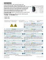
Control Panel Ratings
Control Power:
120-277VAC 50/60 Hz .60A (120V), .34A(277V)
Load Inputs:
120-277VAC 50/60Hz
Load Outputs:
120-277VAC 16A per output
0-10V Outputs:
80mA sink per zone (H2800, H2810, H2814, and H2815 only)
Operating environment: 32
o
F to 104
o
F (0
o
C to 40
o
C)
24V Supply Power:
Limit 13UL (UL = 50mA) for external devices, use LPS-20UL external supply for additional
loading.
Model Numbers
E-FLEX-4-E (4-ckt, DMX, 0-10V)
E-FLEX-8-E (8-ckt, DMX,0-10V)
E-FLEX-4-D (4-ckt, DMX)
E-FLEX-8-D (8-ckt, DMX)
E-FLEX-4-E-TC (4-ckt, DMX, 0-10V, Timeclock)
E-FLEX-8-E-TC (8-ckt, DMX, 0-10V, Timeclock)
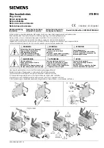
Step 1: Mounting the unit
For indoor use only on a vertical surface!
Remove the panel cover.
Remove the internal high voltage shield which is held in place by two screws on the
left side of the shield.
Mount the panel in an accessible location to allow for end use programming or relay
bypassing.
Install in accordance with all national and local electrical codes.
Mechanical Dimensions
All dimensions shown as inches
E-Flex 4 - 12 in. X 10.5 in.
E-Flex 4 - Keyhole centers 10 in. X 8.5 in.
E-Flex 8 - 12 in. X 16.5 in.
E-Flex 8 – Keyhole centers 10 in. X 14.5 in.
Step 4: 0-10V load wiring
Up to eight IEC SELV/NEC Class 2 isolated 0-10V outputs with 50mA sinking only capability are provided.
These outputs conform to IEC 60929.
Warning:
RISK OF DEATH OR ELECTRIC SHOCK! Before wiring or servicing the unit, make
sure upstream source of power is off via a circuit breaker.
If the high voltage shield is removed, the panel must be accessed by a certified technician following local
codes.
#20-12 AWG wires, strip length – ¼ in., torque – 3.5 lbs.
Connect only to NEC Class 2 circuits. Follow all national and local codes for separation
requirements.
Limit distance run for analog control wiring from controller to last driver. Limiting to a voltage
drop of .3V maximum will help ensure meeting IEC 60929 Annex E standard for minimum light
level at 1V.
E-Flex 4 Example Shown
Step 5: Input bank wiring
Four input banks are provided with a connection for an occupancy sensor, daylight sensor, NEC Class2/PELV
dry contact switch, and E-Flex CapT station. Refer to the instruction sheets provided with the devices.
Warning:
RISK OF DEATH OR ELECTRIC SHOCK! Before wiring or servicing the unit, make sure
upstream source of power is off via a circuit breaker.
If the high voltage shield is removed, the panel must be accessed by a certified technician following local
codes.
Input Bank Wiring:
#20-12 AWG wires, strip length – ¼ in., torque – 3.5 lbs.
CapT station – cable run limit 150 ft. maximum.
Multiple occupancy sensors controlling the same zones must be tied to the same input bank.
DO NOT CONNECT the 24V between two or more panels sharing the same control signals!
Step 6: Switch Configuration – Daylight and Occupancy Sensor Inputs
Two dip switches provide hardware configuration for the daylight and occupancy sensor inputs.
SW1 – Daylight Sensor Inputs
SW1 Position
Daylight Sensor
Active Low* (default)
Active High**
1
Day 1
ON
OFF
2
Day 2
ON
OFF
3
Day 3
ON
OFF
4
Day 4
ON
OFF
SW2 – Occupancy Sensor Inputs
SW2 Position
Occupancy Sensor
Active Low
Active High (default)
1
Occ 1
ON
OFF
2
Occ 2
ON
OFF
3
Occ 3
ON
OFF
4
Occ 4
ON
OFF
*0V reports max light, **10V reports max light.
Step 2: Control power wiring
The E-flex panel operates at 120-277VAC. Use following instructions to wire line voltage to the unit.
Warning:
RISK OF DEATH OR ELECTRIC SHOCK! Before installing input power to the
controller, make sure upstream source of power is off via a circuit breaker.
1.
Use 14 to 12 AWG conductors (depending on breaker rating) to feed the control power wiring. The E-
flex controller draws less than .60A at 120V and
less than .34A at 277V.
2.
The unit power supply has a black (Hot) and white
(Neutral) wire. Wire nut the Hot and Neutral of the
power feed to these wires as shown.
3.
A stud is provided to land the ground wire.
4.
Note: Alternately the unit control power can be
wired from the zone 1 feed rather than a separate
feed. This is especially true if UL924 is applied as
the unit must be powered by the
normal/emergency feed with zone 1 as the first
emergency zone.
Step 3: Line Voltage load wiring
The E-flex panel operates at 120-277VAC. Use following instructions to wire line voltage loads to the unit.
Warning
:
RISK OF DEATH OR ELECTRIC SHOCK! Before installing power to the power feeds,
make sure upstream source of power is off via a circuit breaker.
E-Flex is a feed-through device; this means that each switched output requires Line and Load wires.
Feed-Through Example – 4-circuits, Individual Feeds
Load Wires: Two (2) 14 AWG to 12 AWG. Strip length – 3/8 in., torque – 7 in-lbs.
Neutral and Ground Wires: Wire nut each from feed to load.
Feed-Through Example – 4-circuits, Normal/Emergency, 120V and 277V
Feeds
Voltage Barriers: Separate Normal/Emergency, 120V, and 277V. The voltage barrier is an accessory,
sold separately. Order Lehigh part number A1678.