JABLOTRON
ALARMS
a.s.
Pod
Skalkou
4567/33
46601
Jablonec
n.
Nisou
Czech
Republic
www
.jablotron.com
||
|
The AC-160-DIN Wireless multipurpose relay for DIN rails
The AC-160-DIN wireless multipurpose relay for DIN rails
1 / 2
MLZ54301
The AC-160-DIN wireless multipurpose relay (MFR) is a bi-directional
component of the JABLOTRON 100 system. The MFR copies the status
of selected PG outputs when enrolled to the JA-10xK control panel.
The MFR can also be used as a stand-alone device, then it follows
status of up to 64 one-way communicating detectors of the JA-15x
series and keyfobs of the JA-15xJ MS and JA-16xJ. The MFR then
switches accordingly to the selected mode (modes: extended copy,
impulse, change of status, always switches off and block the relay).
It has galvanically and securely isolated relay contacts for switching
a power load of 230 V / 16 A. This product can only be installed by
a trained technician with a valid certificate issued by an authorised
distributor.
The output relay can also be controlled manually by the button (3)
on the front panel. In stand-alone mode the button serves for enrolling
devices and setting the module properties
.
Installation
The device can only be connected
to mains electricity by a person who has
an adequate electrotechnical qualification.
It
provides
single
pole
switching
and doesn’t provide safety isolation
.
The relay module is meant to be installed
on a DIN rail. There must be a JA-11xR radio
module enrolled to the control panel
to ensure cooperation with the system.
It occupies one position in the JA-100
system.
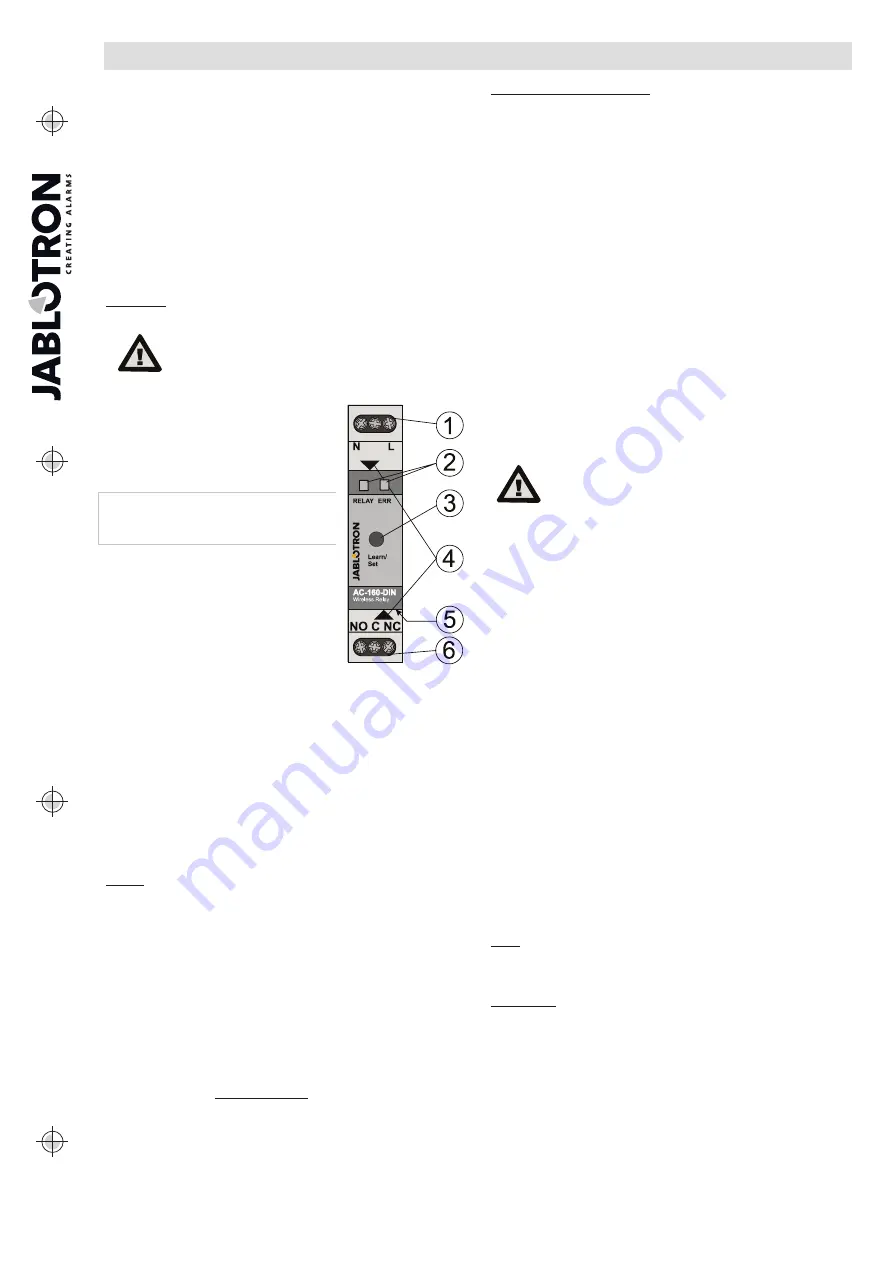
Figure 1: 1 – mains power terminals 230 V AC;
2 – LED indicators; 3 – Learn / Set button;
4 – cover tabs; 5 – connector for AN-868
external antenna; 6 – relay output terminals
1. Install the relay onto the DIN rail.
2. Connect the power wires (230 VAC)
to the terminals (1), and turn the power
on.
3. Proceed according to the control panel
installation manual. Basic procedure:
a.
When the MFR has been turned on,
the ‘RELAY’ indicator lights green.
The
yellow
LED (2)
lights
permanently to indicate the MFR has not been enrolled
to the system yet and that no detector has been enrolled to
the MFR.
b.
Using
F-Link
software, select the required position
in the
Devices
window and launch the enrollment mode
by clicking on the
Enroll
option.
c.
By pressing the
Learn/Set
(3) button longer then 3 s
(until the yellow LED starts flashing) the relay sends
the enrollment signal to the control panel. Enrolling
to the control panel is confirmed when the yellow LED
turns off.
4. Test the MFR function by pressing the button (3).
After approximately 0.5 s the output relay is actived. A switched
relay is indicated by a red LED (‘RELAY’).
5. Connect the controlled device to the terminals (6).
Notes:
The relay goes to standby mode, when the power is disconnected
or communication with the control panel is lost for more than
1 minute. When the MFR has lost communication with an enrolled
device then the restoration interval is 20 minutes. Loss
of communication is indicated by a permanent yellow ‘ERR’ LED.
When the mains or communication with a control panel is restored,
the MFR returns to the status given by pre-defined settings within
2 minutes (for wireless detectors with a periodical link test, such as
the JA-151M, the interval is 9 minutes)
The MFR doesn’t maintain periodical communication with keyfobs.
It is also possible to the MFR to the system by entering
the production code via the F-Link software. A sticker with
the production code is on the rear side of the relay. All digits
in the code are required (example: 1400-00-0000-0001)
JA-18x detectors are not compatible with the relay
Multiple-input detectors such as the JA-150M are always enrolled
to one position and the relay is only triggered by the first input
of the detector. The second input has no effect.
After each press of the Learn/Set button the MFR changes
its status after 0.5 s, as well as when a signal is transmitted or while
entering the MFR’s service mode – indicated by the ‘RELAY’ LED.
When a control panel is already enrolled, the function can be
disabled. See the settings below.
Setting the module properties
The module properties can be set in the
Devices
window
of the
F-Link
software. When at the module position, use
the
Internal settings
option to open a dialogue window where you can
set the following options:
Manual relay control:
Enabled: a short press of the Learn/Set button (3)
changes the relay state (switches ON/OFF). Manual control is always
possible even in a situation when the MFR doesn’t communicate
with the control panel. Manual control can be completely disabled.
Reacts to PG(s):
Enables activation of the MFR by one or more control
panel PG outputs.
Common timer:
Determines the period of time during which the output
relay will be switched ON. The function differs according to the pre-set mode
of the associated detector. This parameter serves for setting the timing of the
switching impulse of an impulse detector or a keyfob. A status-mode type
of detector with an “extended copy” reaction set makes the relay stay active
for the whole time even when the detector goes to standby. The timer can
be set in pre-defined steps or your own time in the F-Link software (from 1s
to 23h 59min 59s).
Enrolled devices:
This window includes 64 positions to detectors
and keyfobs. There are two options to them to the relay: the first is
to enter the production code into the
production code
field. The second
is enrolling them via the Learn/Set button which is described in the
Enrolling the detectors and keyfobs
chapter. In this case it is
recommended to use the internal menu only to check on or maintain
the modes of the enrolled detectors.
The MFR internal settings do not work in
on-line mode. That´s why it is not possible
to enroll devices via F-Link SW sending
an enrollment signal. It is only possible
by entering the serial number and saving
the settings.
Mode:
This option determines how the MFR will react
to the activation of an enrolled device.
None:
the device has no function
Extended copy:
This reaction is only for the detectors.
The MFR will be switched ON for as long as the detector
is activated. After the detector goes to standby mode, the MFR
extends activation with time set by the ‘common timer’ function.
Switch On/Switch Off:
This reaction is only for keyfobs
of the JA-15xJ and JA-16xJ series. The A(C) button switches
the MFR on and the B(D) button switches it off.
Impulse:
detector activation will switch ON the MFR for
a pre-defined time given by the Common timer. The MFR can
be kept switched on as long as the configured keyfob button
is pressed. Up to 60 seconds maximum.
Change status:
detector activation or pressing the configured
keyfob button changes the MFR’s status
Always
switching
off:
detector
activation
or pressing
the configured keyfob button always switches off the MFR if there’s
no active selected PG output in the control panel or a status
detector with Extended copy mode.
Block:
A particular active status-mode detector blocks switching
the MFR by other detectors for its whole activation period. The A(C)
button on an enrolled keyfob blocks the MFR on and the B(D)
button unblocks it. When blocking is over, the relay is activated
again as long as there is a request to switch on the MFR by any
status-mode detector or a PG output. Blocking is indicated
by the flashing green LED. Blocking during other detector activation
is indicated by alternate flashing in green / red of the ‘RELAY’ LED.
Note:
The highest priority of the relay is blocking, next is triggering
a status detector or a PG output and then everything else (timer, switch
on/off, status change), so that a switched on relay can’t be switched off
by, for example, a PG output.
FW upgrade
1. A FW upgrade can be performed by a user with Service
authorisation.
2.
The
F-Link
SW is needed to perform the upgrade.
3. Using a thin tool (screwdriver) slightly press the tab (4) and take off
the relay front cover. It allows access to the Micro USB connector.
4. Connect the PC to the relay using a Micro USB cable.
A FW upgrade can be performed with a connected control panel
or offline with only the MFR connected.
The MFR can be powered by 230 V AC, the USB circuits
are galvanically isolated. A power supply is not required
as the relay is powered via the USB cable from the PC.
5. The relay’s BOOT mode is indicated by flashing the green / red
‘RELAY’ LED.
6. Then continue as if you are doing an upgrade via
F-Link
software:
&RQWUROSDQHOĺ8SJUDGH)LUPZDUH
ĺWKH
FW upgrade file pack
(it is a part of the F-Link installation pack, or it can be independently