Laspaziale S2, Installation Instructions Manual
The Yamaha S2 (Japanese) Owner's Manual is now available for download on our website, completely free of charge. This comprehensive manual provides detailed instructions and essential information for optimizing your experience with the Yamaha S2. Download your manual from manualshive.com to unlock the full potential of your product.
Share
Download


Reviews:
No comments
Related manuals for S2
31876500
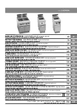
Brand: GGMgastro Pages: 257

F073-C201
Brand: Hoshizaki Pages: 43
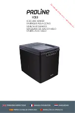
ICE3
Brand: Proline Pages: 40

CB 2001
Brand: BOMANN Pages: 54

MINIGEL 1
Brand: Ugolini Pages: 11

30-32002eco
Brand: C3 Pages: 104

ICE CREAM MAKER
Brand: Bella Pages: 29

RI9343/11
Brand: Saeco Pages: 47

EGRO ONE Top Milk
Brand: Egro Pages: 2

COFFEE CENTER
Brand: West Bend Pages: 40

POWERMark
Brand: Brady Pages: 201

Mini Me
Brand: Dolce Gusto Pages: 20

SC-IM22255
Brand: Scarlett Pages: 26

15"W
Brand: Viking Pages: 12

10001887
Brand: Gaggia Pages: 51

CAFE PC1
Brand: Curtis Pages: 4

Coffee Art
Brand: Schaerer Pages: 76

INS1057
Brand: Insignia Pages: 31


