background image

Operating Instructions and Parts Manual

Square Wheel Belt Grinder

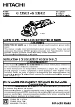
Models: J-4103, J-4126AC

Model J-4126AC

WALTER MEIER (Manufacturing) Inc.

427 New Sanford Road
LaVergne, Tennessee 37086

Part No. M-577000

Ph.: 800-274-6848

Revision  A3  01/2011

www.waltermeier.com

Copyright © 2011 Walter Meier (Manufacturing) Inc.

Model J-4103

Summary of Contents for J-4103

Page 1: ...lt Grinder Models J 4103 J 4126AC Model J 4126AC WALTER MEIER Manufacturing Inc 427 New Sanford Road LaVergne Tennessee 37086 Part No M 577000 Ph 800 274 6848 Revision A3 01 2011 www waltermeier com Copyright 2011 Walter Meier Manufacturing Inc Model J 4103 ...

Page 2: ...ostage prepaid to a location designated by us For the name of the location nearest you please call 1 800 274 6848 You must provide proof of initial purchase date and an explanation of the complaint must accompany the merchandise If our inspection discloses a defect we will repair or replace the product or refund the purchase price at our option We will return the repaired product or replacement at...

Page 3: ...3 Table of Contents Cover Page 1 General Specifications 4 Operating Precautions 5 Setup and Operation 7 Maintenance 10 Wiring Diagrams 12 Replacement Parts 13 Troubleshooting 13 Accessories 17 ...

Page 4: ...and tracking are easily adjustable The Square Wheel Belt Grinder is available in either single speed Model J 4103 or variable speed model Model J 4126AC The variable speed model is controlled by an inverter that provides belt speeds ranging from 0 to 6000 SFPM Specifications Model J 4103 Model J 4126AC Stock Number 577000 577001 Belt Width Length 2 x 72 Inches 2 x 72 inches Belt Speed 4600 SFPM 0 ...

Page 5: ...s with side shields which comply with ANSI Z87 1 specifications Use of eye wear which does not comply with ANSI Z87 1 specifications could result in severe injury from breakage of eye protection 2 Wear proper apparel No loose clothing or jewelry which can get caught in moving parts Rubber soled footwear is recommended for best footing 3 Do not overreach Failure to maintain proper working position ...

Page 6: ...tection See Figure A below 2 Wear leather safety gloves arm guards leather aprons and safety shoes 3 A dust collection system is recommended Operator shall also wear a dust mask at all times See Figure B below 4 Additional precautions may be necessary for grinding materials which are flammable or have other hazardous properties You should always consult the manufacturer of such materials for instr...

Page 7: ...nch or pedestal using the four holes in the base of the grinder Refer to Assembly of Pedestal for machines that are to be pedestal mounted Installation of Work Rest The work rest mounts on the left side of the head casting Attach the work rest using the socket head cap screw provided with the machine The slot in the work rest has a lip against which the cap screw is tightened Place the hole at the...

Page 8: ...achine Model 4126AC NOTE Refer to Figure 4 Use only the inverter controls defined in the following procedures The inverter is pre programmed at the factory and requires no further programming The controls for the Model 4126AC grinder are located on the inverter The ON OFF switch is located on the left side of the inverter Start the grinder by setting the ON OFF switch to ON Press the FWD RUN pushb...

Page 9: ...icult hard to reach areas with the 3 inch by 2 inch or 1 1 2 inch by 2 inch diameter contact wheels Contours and shapes unique parts like propellers and metal furniture OPTIONAL FEATURES Internal contouring The air cushioned dead head is for use on very small radius grinding When connected to a source of shop air 80 90 psi the belt rides on a cushion of air to decrease head and belt wear The dead ...

Page 10: ...clamping screw 11 Lift tension lever to set belt tension 12 Lower and adjust position of upper guard Tighten the upper guard knob Figure 5 Replacement of Contact Wheel Installation of Platen WARNING BE SURE TO SET ON OFF SWITCH OFF TO AVOID PERSONAL INJURY 1 Refer to Figure 6 Lower the tension lever to release belt tension 2 Loosen upper guard knob and swing guard back for clearance 3 Loosen the c...

Page 11: ...belt If the belt tracks either right or left adjustment is required 3 Use an Allen wrench to change the alignment of the idler wheel Turn the idler adjustment screw clockwise to cause the belt to track right Turn the idler adjustment screw counterclock wise to cause the belt to track left 4 Close side panel and secure by turning the knob on the panel Lower the upper belt guard and secure with the ...

Page 12: ...12 Wiring Diagrams Model J 4103 Model 4126AC ...

Page 13: ...t is just taut Contact Wheel Wear 1 Excessive belt tension 1 Set tension so belt is just taut 2 Grinding in one area on belt 2 Use entire work surface of belt when ever possible 3 Excessive grinding deposits 3 Periodically clean interior of grinder on belt and debris in machine Short Belt Life 1 Excessive grinding pressure 1 Allow the belt to do the cutting Excessive pressure dulls the belt and re...

Page 14: ...14 Exploded View Square Wheel Belt Grinder 45 ...

Page 15: ...p 3 8 16 x 5 8 2 18 9055361 Flat Washer Nylon 1 2 I D x 1 O D 1 19 9129861 Scr Socket Head Cap Fll Thrd 3 8 24 x 3 1 20 5046571 Bearing Idler Housing 1 21 9055381 Flat Washer Nylon 3 8 2 22 9010271 O Ring 1 2 1 23 5044651 Cap Idler Housing Pin 1 24 9133041 Set Screw Socket Head 1 4 20 x 1 4 1 25 5046560 Lever Tension 1 26 9133191 Set Screw Nylon Tipped 5 16 18 x 3 4 1 27 9129561 Locknut Hex 3 8 24...

Page 16: ...erter 3ph 440V 50 60Hz 3 9128571 Screw Hex Head 1 2 13 x 1 1 4 5515215 Mount Inverter 1 5 9119481 Terminal Full Closed 1 Parts List Inverter 6 5508073 Nut Lock 10 32 Nylock 4 7 5507934 Box Switch 1 9 9119721 Spade Female 16 14AWG 4 10 9117401 Switch Toggle 1 12 9085061 Dial ON OFF 1 13 9119071 Grip Cord 2 14 5628371 Lock Washer 1 2 1 Ref Part No Number Description Qty ...

Page 17: ...se 1 3 5053601 Reducer 4 x 3 in 1 Woodworkers 5053611 Reducer 4 x 3 in 1 Metal Workers 4 5507534 Clamp Hose 3 in 1 5 5507533 Hose 3 x 5 in 1 6 9128241 Screw HH Cap 3 7 9070361 Knob 2 Ref Part No Number Description Qty 8 5053571 Rail 1 9 9032961 Lock Nut Nylon Insert 4 10 9055411 Washer Nylon 8 11 5053581 Channel 1 12 9057391 Washer Flat 2 13 9056411 Nut Hex Jam 3 14 9062111 Screw SHCS 5 16 18 X 3 ...

Page 18: ...Y POSITION AND SECURE THE MACHINE COULD RESULT IN THE MACHINE TIPPING OVER CAUSING INJURY TO PERSONNEL Figure 15 Contouring Using Small Diameter Contact Wheel There are four mounting holes in the mounting plate on the pedestal The holes on the motor side of the machine are approximately 20 inches apart The holes on the belt guard side of the machine are located approximately inch from the corners ...

Page 19: ...ches apart Belt Guard Holes Approximately 1 2 inch from corners Install two 1 inch long screws 1 2 3 2 Install two 1 3 4 inch screws 3 Ref No Part Number Description Qty 1 J 524808 Pedestal 1 2 9062121 Socket Head Cap Screw 5 16 18 x 1 2 3 5511051 Socket Head Cap Screw 5 16 18 x 1 3 4 2 ...

Page 20: ...WALTER MEIER Manufacturing Inc 427 New Sanford Road LaVergne Tennessee 37086 Ph 800 274 6848 www waltermeier com ...

Reviews: