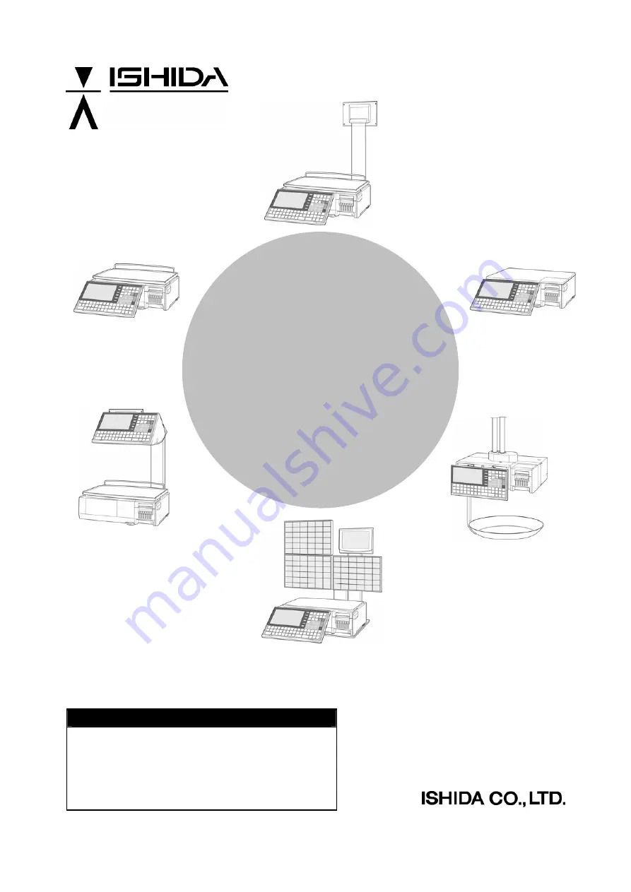
background image


UNI-7


Service Manual 


IMPORTANT 

  Read this manual thoroughly, and do not perform 

installation, operation, maintenance, or inspection 
unless you fully understand all of the contents. 

  Keep this manual in a safe place where you can refer 

to it easily while installing, operating, and carrying out 
maintenance or inspections.


RS-61004-11 


Summary of Contents for UNI-7

Page 1: ...d do not perform installation operation maintenance or inspection unless you fully understand all of the contents Keep this manual in a safe place where you can refer to it easily while installing operating and carrying out maintenance or inspections RS 61004 11 ...

Page 2: ... are reserved No part of this publication may be reproduced stored in a retrieval system or transmitted in any form or by any means mechanical electronic photocopying recording or otherwise without prior written permission of ISHIDA ...

Page 3: ... way connected with the machine whether such claim is based on contract warranty negligence or strict liability ISHIDA assumes no responsibility for the user s programming of this machine or any consequence thereof In no event shall ISHIDA be responsible for warranty repair or other claims regarding the machine unless ISHIDA s analysis confirms that the machines were properly handled stored instal...

Page 4: ...ury Always heed the information provided in this manual Failure to heed precautions can result in personal injury or property damage Indicates a potentially hazardous situation which if not avoided may result in serious injury or death Additionally there may be significant property damage Indicates a potentially hazardous situation where if not avoided may result in minor or moderate injury or in ...

Page 5: ...ety functions Do not hold the connector cover when carrying the machine Dropping the machine may result in injury or cause the machine to break down Do not hold the operation panel or weigh platter when carrying the machine Doing so may cause the operation panel or the platter to break down Do not hold the customer display the when carrying the pole type machine Dropping the machine may result in ...

Page 6: ...lt in injury or cause the cassette to break down Do not press the touch panel with an edged thing Doing so may scratch the panel and cause the machine to break down Do not dispose of batteries with normal household waste Please obey your local regulations when disposing of used batteries iv UNI 7 Service Manual ...

Page 7: ...r contact lenses remove and wash them If the fluid comes into contact with your skin Immediately rinse the area of contact with water and then wash with soap If you notice any skin abnormalities at the area of contact or if any pain persists consult your doctor If the fumes of the fluid are inhaled Immediately move the victim to an area where fresh air is available and have the victim lie down and...

Page 8: ... Chapter 2 ASSEMBLY DRAWINGS 2 1 BENCH TYPE 2 1 2 2 POLE TYPE 2 3 2 3 BAKERY TYPE 2 5 2 4 SELF SERVICE TYPE 2 7 2 5 ELEVATED SINGLE PRINTER TYPE 2 8 2 6 ELEVATED DUAL PRINTER TYPE 2 10 Chapter 3 BLOCK DIAGRAMS 3 1 BLOCK DIAGRAM BENCH POLE TYPE 3 1 3 2 BLOCK DIAGRAM BAKERY TYPE 3 2 3 3 BLOCK DIAGRAM SELF SERVICE TYPE 3 3 3 4 BLOCK DIAGRAM HANGING TYPE 3 4 3 5 BLOCK DIAGRAM ELEVATED TYPE 3 5 Chapter...

Page 9: ...N UNIT 5 14 5 2 POLE TYPE 5 15 5 2 1 POLE UNIT 5 15 5 2 2 CUSTOMER DISPLAY UNIT 5 16 5 3 BAKERY TYPE 5 17 5 3 1 UPPER CASE 5 17 5 4 SELF SERVICE TYPE 5 19 5 4 1 SELF SERVICE PANEL UNIT 5 19 5 4 2 PANEL CONTROL BOARD 5 21 5 5 ELEVATED TYPE 5 22 5 5 1 OPERATION PANEL UNIT FOR DUAL PRINTER 5 22 5 5 2 OPERATION PANEL UNIT FOR SINGLE PRINTER 5 24 5 5 3 PRINTER UNIT FOR DUAL PRINTER 5 25 5 5 4 CUSTOMER ...

Page 10: ...USTOM BARCODE SETTING 7 17 7 6 MENU TILTLE EDITING 7 21 7 7 OPERATION SETTING 7 27 7 8 ERROR PROCESS SETTING 7 29 7 9 ERROR LOG DISPLAY 7 31 7 10 TRACEABILITY SETTING 7 32 7 11 DUAL CURRENCY SETTING 7 33 7 12 PRICE DOUNDING SETTING 7 34 7 12 COUNTRY SETTING 7 35 7 13 FILE SAVE LOAD 7 36 Chapter 8 ADJUSTMENT MODE 8 1 ADJUSTMENT MODE ENTRY 8 1 8 2 KEY CHECK 8 3 8 3 PROGRAM NUMBER 8 5 8 4 MEMORY CLEA...

Page 11: ...T EDITING A 1 OPERATION PANEL AND KEY FUNCTIONS A 1 A 2 NORMAL CHARACTER REGISTRATION A 3 A 3 SPECIAL CHARACTER REGISTRATION A 6 A 4 LINE DELETION A 8 A 5 CHARACTER DELETION A 9 A 6 CHARACTER BACKSPACING A 11 UNI 7 Service Manual ix ...

Page 12: ...TABLE OF CONTENTS x UNI 7 Service Manual ...

Page 13: ...Chapter 1 BASIC INFORMATION 1 BASIC INFORMATION 1 1 OUTER DIMENSIONS FOR EACH TYPE 1 1 1 OUTER DIMENSIONS FOR BENCH TYPE Bench Type UNI 7 Service Manual 1 1 ...

Page 14: ...Chapter 1 BASIC INFORMATION 1 1 2 OUTER DIMENSIONS FOR POLE TYPE Pole Type 1 2 UNI 7 Service Manual ...

Page 15: ...Chapter 1 BASIC INFORMATION 1 1 3 OUTER DIMENSIONS FOR BAKERY TYPE Bakery Type UNI 7 Service Manual 1 3 ...

Page 16: ...Chapter 1 BASIC INFORMATION 1 1 4 OUTER DIMENSIONS FOR SELF SERVICE TYPE Self service Type 1 4 UNI 7 Service Manual ...

Page 17: ...Chapter 1 BASIC INFORMATION 1 1 5 OUTER DIMENSIONS FOR ELEVATED TYPE Elevated Type UNI 7 Service Manual 1 5 ...

Page 18: ...Chapter 1 BASIC INFORMATION 1 1 6 OUTER DIMENSIONS FOR HANGING TYPE Hanging Type 1 6 UNI 7 Service Manual ...

Page 19: ...erator Customer display 7 0 inch color liquid crystal with back light 480 X 234dots Printing method Direct thermal method Thermal head 2 inches 448dots and 8 dots mm Printing speed 100mm second 120mm second Note The printing speed may vary according to label conditions Printing effective size 56mm Label size Label width 30mm to 60mm Label length 20mm to 150mm Number of label cassettes 7 cassettes ...

Page 20: ...ck Prepare a dedicated power source A power supply that generates voltage variation may cause a malfunction Do not stand on the power cable and do not place anything heavy on the cable Doing so may damage the cable resulting in accident or trouble Disconnect power supply before servicing To ensure your personal safety disconnect the power supply before servicing Take precaution against residual el...

Page 21: ...exposed to direct sunlight Places where water or other liquids are easily spilled on the machine Places subject to excessive vibration or unstable foundations Places exposed to direct cold air from air conditioners or refrigerators Places where the floor or foundation is unstable Places subject to a lot of dust or dirt Places with large voltage fluctuations UNI 7 Service Manual 1 9 ...

Page 22: ...Chapter 1 BASIC INFORMATION 1 10 UNI 7 Service Manual ...

Page 23: ...Chapter 2 ASSEMBLY DRAWINGS 2 ASSEMBLY DRAWINGS 2 1 BENCH TYPE UNI 7 Service Manual 2 1 ...

Page 24: ...ACKET CONNECTOR 1 16 SCREW SEAL HEXA 1 53 BASE 1 17 SCREW SEAL 1 54 BUSH NG 1 18 PK 260 1 55 PLATE B RS232C 1 19 HARNESS C4 FRONT LCD 1 56 PLATE B MAGNET IC 1 20 HARNESS C4 REAR LCD 1 57 BLOCK B HINGE SIDE COVER 1 21 HARNESS C4 SENSOR 1 58 FOOT ADJUST 4 22 HARNESS C2 HEAD 1 59 COVER SIDE 1 23 HARNESS S2 MOTOR 1 60 COVER HARNESS 1 24 ACCESSORY PCB SUPPORT 4 61 PK 263 1 25 HARNESS C2 CASSETTE 1 62 L...

Page 25: ...Chapter 2 ASSEMBLY DRAWINGS 2 2 POLE TYPE UNI 7 Service Manual 2 3 ...

Page 26: ...ASE REAR POLE DISPLAY 1 19 HARNESS C4 REAR LCD POLE 1 63 PLATE B BRACKET POLE 1 20 HARNESS C4 FRONT LCD 1 64 BRACKET POLE STAND 1 21 HARNESS C4 SENSOR 1 65 POLE STAND 1 22 HARNESS C2 HEAD 1 66 CASE LINK POLE 1 23 HARNESS S2 MOTOR 1 67 PLATE LINK POLE 4 24 ACCESSORY PCB SUPPORT 4 68 CASE REAR POLE DISPLAY 1 25 HARNESS C2 24V DC POWER 1 69 PK 263 1 26 HARNESS C2 CASSETTE 1 70 LCD 1 27 HARNESS C2 A D...

Page 27: ...Chapter 2 ASSEMBLY DRAWINGS 2 3 BAKERY TYPE UNI 7 Service Manual 2 5 ...

Page 28: ...VER 1 42 COVER SWITCH 1 13 BRACKET POWER 1 43 HARNESS C4 SWITCH ASSEMBLY 1 14 POWER SUPPLY 1 44 BRACKET CONNECTOR ASSEMBLY 1 15 BASE 1 45 PWB PK 265 1 16 BLOCK B HINGE SIDE COVER 1 46 HARNESS S2 5V POWER 1 17 COVER SIDE 1 47 HARNESS S2 LAN 1 18 FOOT LEVEL 4 48 ANTENNA FOR WIRELESS LAN 1 19 PLATE B MAGNETIC 1 49 STICKER LOCATION OUTPUT 1 20 PLATE B RS232C 1 50 STICKER SEAL 1 21 HARNESS C2 POWER ASS...

Page 29: ...G 3 16 COVER JOINT 1 4 SHEET KEYBOARD MEMBRANE 3 17 POLE STAND 1 5 CASE FRONT KEY UNIT 3 18 BASE 1 6 PWB PK 266 1 19 FOOT ADJUST 5 7 PWB PK 267 2 20 BUMPON 1 8 FRAME KEY UNIT 2 21 VIBRATOR ASSEMBLY 6 9 CASE REAR KEY UNIT 1 22 CABLE CLAMP 3 10 CASE REAR KEY UNIT 2 23 HARNESS C2 SERIAL 1 11 CAP RECTANGLE 8 24 NAME PLATE SPEC 1 12 CAP 8 25 FRAME KEY UNIT L 1 13 BRACKET KEY UNIT 1 26 FRAME KEY UNIT R ...

Page 30: ...Chapter 2 ASSEMBLY DRAWINGS 2 5 ELEVATED SINGLE PRINTER TYPE 2 8 UNI 7 Service Manual ...

Page 31: ...1 E ARTH CLAMP 2 67 STICKER SEAL 1 22 VIBRATOR ASSEMBLY 2 68 PWB PK 265 1 23 EARTH CLAMP 1 69 BRACKET CONNECTOR ASSEMBLY 1 24 FRAME PRINTER UPPER 1 70 BRACKET LEVEL 1 25 FRAME PRINTER 1 71 LEVEL UNIT 1 26 HOLDER COVER 1 72 FRAME LEVEL 1 27 BRACKET COVER 1 73 ACCESSROY PCB SUPPORT 4 28 PANEL COVER 2 74 PWB P 999B 1 29 CASE CONTROL REAR 1 75 CASE AD BOARD 1 30 PANEL BUTTON 1 76 SCREW SEAL HEXA 1 31 ...

Page 32: ...Chapter 2 ASSEMBLY DRAWINGS 2 6 ELEVATED DUAL PRINTER TYPE 2 10 UNI 7 Service Manual ...

Page 33: ...RINTER UNIT 1 71 FRAME LEVEL 1 23 PRINTER MODULE ASSEMBLY 1 72 LEVEL UNIT 1 24 PANEL COVER 1 73 BRACKET LEVEL 1 25 BUSH TORQUE 2 74 CASE AD BOARD 1 26 CASE CONTROL REAR 1 75 ACCESSROY PCB SUPPORT 4 27 BUTTON PRINTER 1 76 PWB P 999 1 28 BRACKET CONTROL 1 77 EARTH CLAMP 1 29 POLE STAND 1 78 SCREW SEAL HEXA 1 30 BRACKET POLE STAND 1 79 SCREW SEAL HEXA 1 31 PLATE B BRACKET POLE 1 80 COVER SIDE 1 32 FO...

Page 34: ...Chapter 2 ASSEMBLY DRAWINGS 2 12 UNI 7 Service Manual ...

Page 35: ...Chapter 3 BLOCK DIAGRAMS 3 BLOCK DIAGRAMS 3 1 BLOCK DIAGRAM BENCH POLE TYPE UNI 7 Service Manual 3 1 ...

Page 36: ...Chapter 3 BLOCK DIAGRAMS 3 2 BLOCK DIAGRAM BAKERY TYPE 3 2 UNI 7 Service Manual ...

Page 37: ...Chapter 3 BLOCK DIAGRAMS 3 3 BLOCK DIAGRAM SELF SERVICE TYPE UNI 7 Service Manual 3 3 ...

Page 38: ...Chapter 3 BLOCK DIAGRAMS 3 4 BLOCK DIAGRAM HANGING TYPE 3 4 UNI 7 Service Manual ...

Page 39: ...Chapter 3 BLOCK DIAGRAMS 3 5 BLOCK DIAGRAM ELEVATED TYPE Single Printer UNI 7 Service Manual 3 5 ...

Page 40: ...Chapter 3 BLOCK DIAGRAMS Dual Printer 3 6 UNI 7 Service Manual ...

Page 41: ... 40 GND 3 4 DC 5V power supply for LCD 6 8 10 12 13 15 17 19 20 LCD control signal 21 22 AC power supply for LCD 23 DC 10V power supply for LCD 24 DC 15V power supply for LCD 27 DC 15V power supply for LCD backlight 28 29 Light control signal for LCD backlight 30 External buzzer signal 31 Vibration signal 32 33 DC 5V 34 39 Membrane key control signal PK 261 XJ3 XJ2 No Signal Name Direction Opposit...

Page 42: ...No Signal Name Direction Opposite Side 1 2 5 7 9 11 14 16 29 30 GND 3 4 DC 5V power supply for LCD 6 8 10 12 13 15 17 18 19 LCD control signal 20 21 AC power supply for LCD 22 DC 10V power supply for LCD 23 DC 15V power supply for LCD 26 DC 15V power supply for LCD backlight 27 28 Light control signal for LCD backlight 24 25 DC 5V PK 263 XJ1 XJ6 No Signal Name Direction Opposite Side 1 D 2 D 3 DC ...

Page 43: ...Opposite Side 1 BAT 2 GND Unused XJ9 No Signal Name Direction Opposite Side 1 6 For CPLD writing Unused XJ10 No Signal Name Direction Opposite Side 1 DC 5V 2 GND Unused XJ11 No Signal Name Direction Opposite Side 1 DC 5V 2 GND 3 TxD 4 RTS 5 RxD 6 CTS Unused XJ12 No Signal Name Direction Opposite Side 1 DC 5V 2 GND Unused UNI 7 Service Manual 4 3 ...

Page 44: ...rmal head XJ15 No Signal Name Direction Opposite Side 1 B 2 B 3 A 4 A 5 6 DC 24V Stepping motor for label feeding XJ16 No Signal Name Direction Opposite Side 1 Peel sensor DC 5V 2 Peel sensor LED_GND 3 Peel sensor LED_VCC 4 Peel sensor SENS_IN 5 Peel sensor GND 6 Label sensor DC 5V 7 Label sensor LED_GND 8 Label sensor LED_VCC 9 Label sensor SENS_IN 10 Label sensor GND Peel sensor Label sensor 4 4...

Page 45: ...awer 1 XJ21 No Signal Name Direction Opposite Side 1 Cassette 0 LED 2 Cassette 0 SENS_IN 3 Cassette 1 LED 4 Cassette 1 SENS_IN 5 Cassette 2 LED 6 Cassette 2 SENS_IN 7 Cassette 3 LED 8 Cassette 3 SENS_IN 9 GND Cassette sensor XJ22 No Signal Name Direction Opposite Side 1 2 3 DC 24V main power supply 4 5 6 GND Switching power supply XJ23 No Signal Name Direction Opposite Side 1 2 DC 24V 3 4 GND Unus...

Page 46: ...S XJ24 No Signal Name Direction Opposite Side 13 38 DC 3 3V 1 50 GND Others CF control signal XJ25 No Signal Name Direction Opposite Side 2 USB_VBUS 4 USB_D 6 USB_D 8 USB_GND 10 NONE 1 VBUS 3 D 5 D 7 GND 4 6 UNI 7 Service Manual ...

Page 47: ... 11 14 16 18 25 26 40 GND 3 4 DC 5V power supply for LCD 6 8 10 12 13 15 17 19 20 LCD control signal 21 22 AC power supply for LCD 23 DC 10V power supply for LCD 24 DC 15V power supply for LCD 27 DC 15V power supply LCD backlight 28 29 Light control signal for LCD backlight 30 External buzzer signal 31 Vibration signal 32 33 DC 5V 34 39 Membrane key control signal PK 260 XJ1 XJ4 No Signal Name Dir...

Page 48: ...rs LCD control signal LCD XJ6 No Signal Name Direction Opposite Side 1 DC 5V 2 GND LCD backlight XJ8 No Signal Name Direction Opposite Side 1 2 3 4 5 6 7 8 Key scanning KS0 KS7 9 10 11 12 13 14 15 16 17 18 19 Key data KD0 KD10 20 Unused Membrane key XJ9 No Signal Name Direction Opposite Side 1 DC 5V 2 GND Unused XJ10 11 No Signal Name Direction Opposite Side 1 DC 5V for vibration 2 GND Vibration u...

Page 49: ...6 DC 15V power supply for LCD backlight 27 28 Light control signal for LCD backlight 24 25 DC 5V PK 260 XJ4 XJ2 No Signal Name Direction Opposite Side 1 GND 2 DIM 3 DC 5V Unused XJ3 No Signal Name Direction Opposite Side 2 20 DC 5V 1 21 GND 25 DC 5V power supply for LCD 26 LCD GND 10 11 AC power supply for LCD 3 DC 10V power supply for LCD 4 DC 15V power supply for LCD Others LCD control signal LC...

Page 50: ...IRELESS LAN BOARD PK 265 XJ1 No Signal Name Direction Opposite Side 1 DC 5V 2 GND PK 260 XJ12 XJ2 No Signal Name Direction Opposite Side 1 TX 2 TX 3 RX 6 RX 10 LEDR 11 LEDL 4 7 13 14 GND 9 12 DC 3 3V PK 260 XJ3 4 10 UNI 7 Service Manual ...

Page 51: ...nal Name Direction Opposite Side 1 DC 5V 2 TxD 3 RxD 4 P_GND PK 260 XJ11 XJ3 XJ4 No Signal Name Direction Opposite Side 1 DC 5V 2 GND 3 4 5 6 Membrane key control signal PK 267 XJ1 XJ5 No Signal Name Direction Opposite Side 1 2 3 4 5 6 Key scan KS0 KS5 7 8 9 10 11 12 Key data KD0 KD5 Membrane key XJ6 XJ7 No Signal Name Direction Opposite Side 1 DC 5V 2 GND Vibration unit UNI 7 Service Manual 4 11 ...

Page 52: ...ARD PK 267 XJ1 No Signal Name Direction Opposite Side 1 DC 5V 2 GND 3 4 5 6 Membrane key control signal PK 266 XJ3 XJ4 XJ2 No Signal Name Direction Opposite Side 1 2 3 4 5 6 Key scan KS0 5 7 8 9 10 11 12 Key data KD0 5 Membrane key 4 12 UNI 7 Service Manual ...

Page 53: ...ten position sensor 6 19 20 DC 24V Head drive power supply 7 8 9 16 17 18 Thermal head control signal 10 DC 5V 15 TH Thermistor input signal 21 MOTOR_A 22 MOTOR_B 23 MOTER_A 24 MOTER_B 26 CUTS Cutter sensor 27 CUTB Cutter motor 28 CUTA Cutter motor PK 269 XJ1 XJ4 No Signal Name Direction Opposite Side 1 CD 24V 2 DC 24V 3 DC 24V 4 GND 5 GND 6 GND PK 260 XJ23 UNI 7 Service Manual 4 13 ...

Page 54: ...GND 9 D_GND 10 U_GND PK 260 XJ25 XJ6 No Signal Name Direction Opposite Side 1 D_Vbus Port4 2 D_Vbus Port3 3 D_D Port4 4 D_D Port3 5 D_D Port4 6 D_D Port3 7 D_GND Port4 8 D_GND Port3 9 Key 10 D_GND Port3 Unused XJ1 No Signal Name Direction Opposite Side 1 SG 2 DC 5V 3 4 5 6 7 8 FROM write signal Unused 4 14 UNI 7 Service Manual ...

Page 55: ... signal 21 MOTOR_B 22 MOTOR_A 23 MOTER_B 24 MOTER_A 26 CUTS Cutter sensor 27 CUTB Cutter motor 28 CUTA Cutter motor PK 268 XJ2 XJ2 No Signal Name Direction Opposite Side 1 GND 2 CUTS Cutter sensor 3 CUTB Cutter motor 4 CUTA Cutter motor Printer unit XJ2 No Signal Name Direction Opposite Side 1 PS Paper sensor receiver 2 VPS Paper sensor emmiter 3 4 11 12 13 14 25 GND 5 HS Platen position sensor 6 ...

Page 56: ...Chapter 4 ELECTRICAL SIGNALS No Signal Name Direction Opposite Side 15 TH Thermistor input signal 21 MOTOR_A 22 MOTOR_B 23 MOTER_A 24 MOTER_B 4 16 UNI 7 Service Manual ...

Page 57: ...hapter 4 ELECTRICAL SIGNALS 4 9 SCALE BOARD PK 999 XJ2 No Signal Name Direction Opposite Side 1 D 2 D 3 DC 12V 4 GND 5 FG 6 Not connected 7 Not connected 8 Not connected PK 260 UNI 7 Service Manual 4 17 ...

Page 58: ...Chapter 4 ELECTRICAL SIGNALS 4 18 UNI 7 Service Manual ...

Page 59: ... the cassette unit from the main unit 3 Raise the operation panel and remove the screw fixing the hinge cover 4 Make the operation panel angle about 45 and pull out the hinge cover 5 Remove the five screws blue two tapping screws red and one TP screw green 6 Remove the upper case Upper case Weigh platter holder Reverse this procedure for assembly UNI 7 Service Manual 5 1 ...

Page 60: ...tion 5 1 1 2 Remove the four screws fixing the weigh platter holder 3 Remove the weigh platter holder Motor STP 29D1026 Main board PK 260 AD board P 999 in the die cast Power supply ZWS150PAF 24 J Load cell CLC 25N Weigh platter holder Motor STP 29D1026 Reverse this procedure for assembly 5 2 UNI 7 Service Manual ...

Page 61: ...Y 5 1 3 MAIN BOARD 1 Unplug all harnesses connected to the main board 2 Remove the three screws fixing the main board 3 Squeeze the two spacers to remove the main board Reverse this procedure for assembly UNI 7 Service Manual 5 3 ...

Page 62: ...tion panel 2 Remove the bottom case of the operation panel 3 Unplug all harnesses and remove the fixing screws to detach the touch panel LCD with the bracket 4 Unplug the harnesses and peel off the vibrator attached with the double faced tape Bottom case Display Key control board PK 261 Vibrator 5 4 UNI 7 Service Manual ...

Page 63: ...Chapter 5 MACHINE DISASSEMBLY TFT touch panel LCD Membrane keys Reverse this procedure for assembly UNI 7 Service Manual 5 5 ...

Page 64: ...move the four screws fixing the weigh platter holder 3 Remove the weigh platter holder and unplug the harness connected with the main board 4 Detach the customer display unit 5 Detach the display control board and TFT LCD Weigh platter holder TFT LCD AT070TN07 Display control board PK 263 Reverse this procedure for assembly 5 6 UNI 7 Service Manual ...

Page 65: ...ower the thermal head unit by pushing down the lever 5 Carefully remove the two screws fixing the label sensor unit so as not to drop or lose the inserted collars 6 Unplug the harness 7 This photo shows the breakdown of the sensor unit 8 Remove the screw fixing the bracket Thermal head unit Printer lid Label sensor Receiver Reverse this procedure for assembly UNI 7 Service Manual 5 7 ...

Page 66: ...Remove the screw and unplug the harness to remove the peel sensor receiver Peel sensor Emitter Peel sensor Receiver Reverse this procedure for assembly 5 1 8 CASSETTE SENSOR 1 Pull out the cassette unit from the main unit 2 Remove the two screws and unplug the harness to remove the cassette sensor Cassette sensor Reverse this procedure for assembly 5 8 UNI 7 Service Manual ...

Page 67: ...e unit from the main unit 2 Squeeze the springs by holding up the head unit and pull out the thermal head unit 3 Unplug the connector and remove the two screws 4 This photo shows the breakdown of the thermal head unit Reverse this procedure for assembly UNI 7 Service Manual 5 9 ...

Page 68: ...ove the hexagon socket head bolt fixing the load cell unit 3 Remove the two hexagon socket head bolts at the other end and detach the load cell unit 4 Remove the two screws to remove the die cast bracket 5 Unplug the harnesses and squeeze the two spacers green to detach the AD board 5 10 UNI 7 Service Manual ...

Page 69: ...is procedure for assembly 5 1 11 POWER SUPPLY UNIT 1 Disengage the five hooks at the bottom of the machine using a slotted screwdriver 2 Detach the customer display unit and remove the two screws fixing the power supply unit 3 Remove the power supply unit Reverse this procedure for assembly UNI 7 Service Manual 5 11 ...

Page 70: ... screws fixing the side cover 2 Detach the side cover 3 Remove the two screws fixing the plate 4 Remove the screw fixing the cable fastener 5 Remove the plate 6 Remove the motor 7 Unplug the connector 8 Remove the timing belt from the pulley 5 12 UNI 7 Service Manual ...

Page 71: ...Chapter 5 MACHINE DISASSEMBLY 9 Remove the motor unit Reverse this procedure for assembly UNI 7 Service Manual 5 13 ...

Page 72: ...n the main unit 3 Unplug the LAN connector 4 Unplug the connector from the main board 5 The cable connected with the main board and the LAN cable are unplugged 6 Turn to remove the antenna 7 When removing the LAN board remove the two screws 8 This photo shows the constituent parts for the wireless LAN unit Reverse this procedure for assembly 5 14 UNI 7 Service Manual ...

Page 73: ...blind plate located on the bottom of the pole unit 2 Remove the three hexagon socket head bolts and separate the pole unit from the machine 3 Unplug the display harness connector on the main board to remove the pole unit Rear case Reverse this procedure for assembly UNI 7 Service Manual 5 15 ...

Page 74: ... rear case of the customer display unit 2 Detach the front panel of the customer display unit 3 Unplug the connector 4 Remove the two screws and unplug the two harnesses 5 Remove the display control board Display control board PK 263 Reverse this procedure for assembly 5 16 UNI 7 Service Manual ...

Page 75: ...ews located at the rear side of the top cover 3 Disengage the two hooks red and lift to remove the top cover 4 Raise the operation panel and remove the screw fixing the hinge cover 5 Make the operation panel angle about 45 and pull out the hinge cover 6 Remove the six screws fixing the upper case Top cover UNI 7 Service Manual 5 17 ...

Page 76: ...Chapter 5 MACHINE DISASSEMBLY 7 Lift to remove the upper case Reverse this procedure for assembly 5 18 UNI 7 Service Manual ...

Page 77: ...y lay down the machine and self service panel unit so that you can work from the bottom 2 Remove the screw fixing the cable clamp and the grounding terminal 3 Remove the two screws fixing the blind plate 4 Detach the blind plate and unplug the connector Blind plate UNI 7 Service Manual 5 19 ...

Page 78: ...Chapter 5 MACHINE DISASSEMBLY 5 Remove the two screws fixing the cable clamps 6 Separate the self service panel unit from the machine Self service panel unit 5 20 UNI 7 Service Manual ...

Page 79: ...PANEL CONTROL BOARD 1 Lift to disengage the two hooked places and detach the blind cover of the self service panel unit 2 Remove the four screws to detach the rear cover Rear cover Panel control board Blind cover UNI 7 Service Manual 5 21 ...

Page 80: ... two screws located on the bottom of the operation panel unit 2 Remove the two screws located at the customer display side 3 Remove the screw located on the bottom of the operation panel unit 4 Slide the roll holder release lever in the arrow direction Operation panel 5 22 UNI 7 Service Manual ...

Page 81: ... roll holder 7 Remove the screw located inside of the operation panel unit 8 Detach the operation panel 9 This photo shows the rear side of the operation panel 10 This photo shows the inside of the operation panel unit and the rear side of the operation panel Roll holder UNI 7 Service Manual 5 23 ...

Page 82: ... Remove the two screws located at the customer display side 3 Remove the screw located on the bottom of the operation panel unit 4 peel off the blind plate 5 Remove the two screws fixing the roll holder 6 Pull out the holder 7 Remove the screw fixing the operation panel 8 Detach the operation panel Operation panel 5 24 UNI 7 Service Manual ...

Page 83: ...the roll holder is removed from the operation panel unit Refer to section 5 5 1 2 Also make sure that the operation panel unit is disassembled Refer to section 5 5 1 3 Remove the two screws fixing the printer unit 4 Detach the printer unit Printer UNI 7 Service Manual 5 25 ...

Page 84: ...e the two screws fixing the customer display unit 2 Remove the two screws blue and loosen the other two screws green 3 Detach the customer display unit and remove the four fixing screws 4 Open the customer display unit Roll holder 5 26 UNI 7 Service Manual ...

Page 85: ...IEW 5 5 5 ELEVATED UNIT 1 Turn to remove the level adjusting foot 2 Remove the three screws fixing the pole bottom cover 3 Remove the three hexagon socket head bolts fixing the elevated unit UNI 7 Service Manual 5 27 ...

Page 86: ...ING TYPE 5 6 1 HANGING POLE 1 Disengage the joint section to remove the weigh platter unit 2 Remove the weigh platter unit 3 Remove the two screws fixing the hanging pole cover Hanging pole cover Weigh platter unit 5 28 UNI 7 Service Manual ...

Page 87: ... the bolts fixing the pole from the ceiling and the pole from the main unit 5 These photos show the front side and rear side views of the main unit Front Side View Rear Side View Reverse this procedure for assembly UNI 7 Service Manual 5 29 ...

Page 88: ...the operation panel and remove the four fixing screws 2 Remove the front cover of the main unit 3 Unplug all harnesses connected with the main board and remove the five fixing screws Front cover Reverse this procedure for assembly 5 30 UNI 7 Service Manual ...

Page 89: ...r of the main unit 3 Raise the operation panel and remove the two upper screws and loosen the two lower screws 4 Unplug the keyboard harness from the main board and remove the screw for the cable clamp 5 Remove the operation panel from the main unit Front cover Operation panel Reverse this procedure for assembly UNI 7 Service Manual 5 31 ...

Page 90: ...t and rear stainless housings 2 Make sure that the operation panel is removed Refer to section 5 6 3 3 Remove the cassette unit from the main unit and also remove the printer cover 4 Remove the printer frame Front housing Rear housing Front cover Printer cover Printer frame 5 32 UNI 7 Service Manual ...

Page 91: ...MACHINE DISASSEMBLY 5 Remove the ten screws fixing both front and rear stainless steel housings 6 Slide to remove both front and rear stainless steel housings Front housing Rear housing UNI 7 Service Manual 5 33 ...

Page 92: ...s connected with the display control board located inside of the rear housing 8 These photos show the front and rear views Main board Printer unit Motor unit Printer unit Power supply unit Reverse this procedure for assembly 5 34 UNI 7 Service Manual ...

Page 93: ...nless steel case 2 Slide to remove the rear case of the main unit 3 Unplug all harnesses connected with the power supply board and carefully remove the four fixing screws so as not to drop the collars behind Rear case Front case Rear case Reverse this procedure for assembly UNI 7 Service Manual 5 35 ...

Page 94: ...el cases are removed Refer to section 5 6 4 2 Remove the six screws fixing the upper case 3 Detach the upper case and unplug the harness 4 Remove the three screws fixing the load cell board housing Front case Rear case Load Cell board housing Reverse this procedure for assembly 5 36 UNI 7 Service Manual ...

Page 95: ... 6 7 MOTOR UNIT 1 Make sure that the rear stainless steel case is removed Refer to section 5 6 4 3 Remove the power supply unit Refer to section 5 6 5 4 Remove the four fixing screws to detach the motor unit UNI 7 Service Manual 5 37 ...

Page 96: ...Chapter 5 MACHINE DISASSEMBLY 5 38 UNI 7 Service Manual ...

Page 97: ... 6 MECHANICAL ADJUSTMENT 6 1 FOUR CORNER LIMIT SPACE Adjust the limit spaces at four corners of the weigh platter holder to become the following values 1 2mm 2 2mm 3 2 5mm 4 3 2mm 4 1 Weigh platter holder 2 3 UNI 7 Service Manual 6 1 ...

Page 98: ...it 2 Turn the cassette unit upside down 3 Loosen the two screws and move the magnet back and forth for adjustment Be sure to tighten the screws after adjustment Check that the cassette unit is securely fixed by the magnet Label guide Winding bobbin Print roller Roll holder Magnet Bottom of cassette Magnet 6 2 UNI 7 Service Manual ...

Page 99: ... 3 GEAR ENGAGEMENT 1 Make sure that the weigh platter holder is removed 2 Loose the two screws to move the pulley to the appropriate position for better engagement Be sure to tighten the screws after adjustment UNI 7 Service Manual 6 3 ...

Page 100: ...NICAL ADJUSTMENT 6 4 SUPPORT ROLLER 1 Remove the three screws fixing the side cover 2 Remove the side cover 3 Loosen the screw fixing the support roller Be sure to tighten it after adjustment 6 4 UNI 7 Service Manual ...

Page 101: ... unit from the main body 2 This photo shows the position of the thermal head unit 3 Loosen the two screws and move the thermal head unit back and forth and around for position adjustment Be sure to tighten the screws after adjustment Thermal head unit UNI 7 Service Manual 6 5 ...

Page 102: ... thermal head unit 4 Loosen the two screws to adjust the gap between the bracket and the left end of the thermal head 5 1When using the backing paper of up to 62mm width adjust the gap between the bracket and the left end of the thermal head to be 2mm 0 5mm 5 2When using the backing paper of 64mm width adjust the gap between the bracket and the left end of the thermal head to be 3mm 0 5mm Thermal ...

Page 103: ... 7 SETUP MODE 7 1 ENTERING SETUP MODE 1 Press the SETUP button on the Menu Select screen 2 The Setup Menu screen appears Press the b button when changing pages 3 The next setup menu screen appears UNI 7 Service Manual 7 1 ...

Page 104: ...apter 7 SETUP MODE 4 Enter 495344 and press the PLU key on the key sheet to enter Service Mode Î Hidden menus come up on the screen Press the b or a button when changing the pages 7 2 UNI 7 Service Manual ...

Page 105: ...screen 2 The Cassette screen appears Press the c or d button to scroll the table on the screen up or down Press the f or e button to scroll the table on the screen to right or left 3 Press to select a desired cassette number field EXAMPLE Select cassette number 3 UNI 7 Service Manual 7 3 ...

Page 106: ...UP MODE 4 Press to select either Format No or Label Spec 5 Press the FORMAT EDIT button 6 The Label Format Basic screen appears Press the EDIT button 7 The following text edit screen appears 7 4 UNI 7 Service Manual ...

Page 107: ...edited name is shown on the screen ITEM NO Enter a numeric value and press this field WIDTH Enter a numeric value and press this field HEIGHT Enter a numeric value and press this field LABEL NO Enter a numeric value and press this field UNIT NO Enter a numeric value and press this field 9 Select a desired print unit data by using the or button UNI 7 Service Manual 7 5 ...

Page 108: ...a to a desired direction press the c d e f buttons or enter desired numeric values and press the X Axis and Y Axis fields 11 To display the Label Format Unit screen press the UNIT tab To change the pages press the b or a button 7 6 UNI 7 Service Manual ...

Page 109: ... a value for each item enter a desired numeric value and press the corresponding field 13 To select a desired print unit data either press either or button or enter the numeric data and press the UNIT No field UNI 7 Service Manual 7 7 ...

Page 110: ...Chapter 7 SETUP MODE 14 To display the List Unit screen just press the UNIT No field without numeric entry To change the pages press either b or a button 7 8 UNI 7 Service Manual ...

Page 111: ...iew screen press the PREVIEW tab To display the detail image press the DETAIL IMAGE button To move the format position to a desired direction press the c d e f buttons 16 Press the ESC key on the key sheet exit from the current menu UNI 7 Service Manual 7 9 ...

Page 112: ...lue and press this field BACK FEED Press to select either NO or YES Select one of the following types 0 No use SENSOR TYPE 1 Label SENSOR DISTANCE Enter a numeric value and press this field PRINT DIRECTION Press to select either NORMAL or REVERSE PREPRINT FEED Enter a numeric value and press this field Select one of the following print speeds 1 80mm sec PRINT SPEED 2 100mm sec PRINT DENSITY Select...

Page 113: ...eld on the setup menu screen 2 The Label Format List screen appears 3 Press to select a desired format field and press the DETAIL button 4 The Label Format Basic screen appears Refer to steps 6 through 16 in section 7 2 for further procedures UNI 7 Service Manual 7 11 ...

Page 114: ...d field and press the PRINT CONTROL button EXAMPLE LABEL FORMAT 2 6 Press to select a desired field for each print related item on the screen Press the POSITION tab and press to select a desired field for each control related item Press the Return button 7 12 UNI 7 Service Manual ...

Page 115: ...at the Barcode POS Flag screen is displayed If not displayed press the POS FLAG tab Enter a desired numeric value for each item and press the corresponding field 3 Press the POS CODE tab to display the Barcode POS Code screen Then select a desired POS code type by using the and buttons UNI 7 Service Manual 7 13 ...

Page 116: ...7 RSS14STO 8 RSS LIMITED 9 RSS EXPANDED POS CODE TYPE 10 ITF 4 Press the POS FORMAT tab to display the Barcode Format selection screen The following Barcode Format list screen appears Press to select a desired field to determine the barcode format Press either b or a button to change the pages 7 14 UNI 7 Service Manual ...

Page 117: ...by using the and buttons Select one of the following RSS expanded formats 1 01 3922 3202 RSS EXPANDED FORMAT 2 01 3922 3202 15 6 Press the ITEM CODE tab to display the Item Code screen Press to select the code digits for each digit set UNI 7 Service Manual 7 15 ...

Page 118: ...Chapter 7 SETUP MODE 7 Press the Return button to return to the Menu Select screen 7 16 UNI 7 Service Manual ...

Page 119: ...G 1 Press the CUSTOM BARCODE field on the screen 2 The Custom Barcode List screen appears Press the NEW button on the screen 3 The following confirmation screen appears Press the ENTER button on the screen for confirmation UNI 7 Service Manual 7 17 ...

Page 120: ...appears Press the EDIT button on the screen 5 The following text edit screen appears Enter a desired text according to the procedure described in Appendix Text Editing EXAMPLE CUST BARCODE 1 Press the ESC key on the key sheet 7 18 UNI 7 Service Manual ...

Page 121: ... The Custom barcode screen with edited title name appears Then press the selected highlighted field on the screen The following ID list screens appear Press either b or a button to change the pages UNI 7 Service Manual 7 19 ...

Page 122: ... EXAMPLE PLU No Then the following screen appears To continue further registration press to select a desired field on the screen EXAMPLE 2 Press to select a next desired item on the list To end registration press the Return key on the screen 7 20 UNI 7 Service Manual ...

Page 123: ...E EDITING 1 Press the MENU EDIT field on the screen 2 The Menu Title Operate screen appears Press either b or a button to change the pages Press to select a desired field on the screen and press the EDIT button UNI 7 Service Manual 7 21 ...

Page 124: ... Enter a desired text according to the procedure described in Appendix Text Editing EXAMPLE ACCUMULATION 1 Press the ESC key on the key sheet The following confirmation screen appears Press the SAVE button on the screen for confirmation 7 22 UNI 7 Service Manual ...

Page 125: ...r 7 SETUP MODE 4 Press the TOTAL tab on the screen Press either b or a button to change the pages 5 Press the PROGRAM tab on the screen Press either b or a button to change the pages UNI 7 Service Manual 7 23 ...

Page 126: ...Chapter 7 SETUP MODE 7 24 UNI 7 Service Manual ...

Page 127: ...Chapter 7 SETUP MODE 6 Press the SETUP tab on the screen Press either b or a button to change the pages UNI 7 Service Manual 7 25 ...

Page 128: ...Chapter 7 SETUP MODE 7 Press the ADJUST tab on the screen Press either b or a button to change the pages 7 26 UNI 7 Service Manual ...

Page 129: ... on the screen 2 The Operation Setting Call screen appears Then press to select a desired field for each item 3 Press the PRODUCTION tab on the screen The Operation Setting Product screen appears Then press to select a desired field for each item UNI 7 Service Manual 7 27 ...

Page 130: ...Chapter 7 SETUP MODE 4 Press the TIMER tab on the screen The Timer Setting screen appears Then enter a desired numeric value for each item and press the corresponding field 7 28 UNI 7 Service Manual ...

Page 131: ... the ERROR PROCESS field on the screen 2 The Error Process Issue screen appears Press to select a desired field for each item 3 Press the CALL TIME tab to display the Error Process Call screen Then press to select a desired field UNI 7 Service Manual 7 29 ...

Page 132: ...Chapter 7 SETUP MODE 4 Select the COMMON tab to display the Error Process Common screen Then press to select a desired field 7 30 UNI 7 Service Manual ...

Page 133: ...Chapter 7 SETUP MODE 7 9 ERROR LOG DISPLAY 1 Press the ERROR LOG field on the screen 2 The Error Log Display screen appears Press the b or a button when changing the pages UNI 7 Service Manual 7 31 ...

Page 134: ...pter 7 SETUP MODE 7 10 TRACEABILITY SETTING 1 Press the TRACEABILTY SETUP field on the screen 2 The Traceability screen appears Then press to select a desired field for each item 7 32 UNI 7 Service Manual ...

Page 135: ...RENCY SETTING 1 Press the DUAL CURRENCY field on the screen 2 The Dual Currency screen appears Then enter a desired numeric value for each input item and press to select a desired field for each selection item UNI 7 Service Manual 7 33 ...

Page 136: ...pter 7 SETUP MODE 7 12 PRICE DOUNDING SETTING 1 Press the PRICE ROUNDING field on the screen 2 The Price Rounding screen appears Then press to select a desired field for each item 7 34 UNI 7 Service Manual ...

Page 137: ...Chapter 7 SETUP MODE 7 12 COUNTRY SETTING 1 Press the COUNTRY field on the screen 2 The Country screen appears Then press to select a desired country and language UNI 7 Service Manual 7 35 ...

Page 138: ...s inserted into the USB port located in the connector cover of he main body 1 Press the FILE SV LD field on the screen 2 The External File Input screen appears for loading the USB memory data to the main memory To display the File InOut Detail screen press the DETAIL button Press to select a desired field for each item 7 36 UNI 7 Service Manual ...

Page 139: ... main memory data to the USB memory Be sure to press to select a desired data type in the DATA field Press to select a desired field for each item 4 Press the EXT DATA DEL tab to display the external data delete screen Be sure to press to select a desired data type in the DATA field UNI 7 Service Manual 7 37 ...

Page 140: ...Chapter 7 SETUP MODE 5 Press the INTERNAL INIT tab to display the data initialization screen Press the b or a button when changing the pages 7 38 UNI 7 Service Manual ...

Page 141: ...Chapter 7 SETUP MODE UNI 7 Service Manual 7 39 ...

Page 142: ...UP MODE 6 Press to select desired files for initialization and press the EXECUTE button 7 The following confirmation screen appears Then press the EXEC button to execute file initialization 7 40 UNI 7 Service Manual ...

Page 143: ... Press the ADJUST button on the Menu Select screen 2 The Adjustment Menu screen appears 3 Enter 495344 and press the PLU key on the key sheet to enter Service Mode Î Hidden menus come up on the screen Press the b or a button when changing the pages UNI 7 Service Manual 8 1 ...

Page 144: ...Chapter 8 ADJUSTMENT MODE 8 2 UNI 7 Service Manual ...

Page 145: ...HECK field on the screen 2 The Key check screen appears Press any keys on the membrane key sheet and confirm that the corresponding key colors on the screen change into green 3 Press the VIBRATOR tab to display the Key Vibrator screen UNI 7 Service Manual 8 3 ...

Page 146: ...Chapter 8 ADJUSTMENT MODE Press to select whether or not to enable the vibration function Then press the or button to get a desired value 8 4 UNI 7 Service Manual ...

Page 147: ...Chapter 8 ADJUSTMENT MODE 8 3 PROGRAM NUMBER 1 Press the PROGRAM No field on the screen 2 The Program Number screen appears Then confirm the program numbers used in this machine UNI 7 Service Manual 8 5 ...

Page 148: ...E 8 4 MEMORY CLEAR 1 Press the MEMORY CLEAR field on the screen 2 The Memory Clear screen appears 3 To clear the master data press the CLEAR button 4 To initialize the system data press the INIT button 8 6 UNI 7 Service Manual ...

Page 149: ...Chapter 8 ADJUSTMENT MODE 5 To set the test data press the SET button 6 The following confirmation screen appears Then press the EXEC button for execution UNI 7 Service Manual 8 7 ...

Page 150: ...d on the screen 2 The Printer Head screen appears Then select a desired printer by using either or button Enter a desired numeric value for each item and press the corresponding field Select a desired test print type and head type by using either or button 8 8 UNI 7 Service Manual ...

Page 151: ...ric value for each item and pressing the corresponding field Press a desired field to select whether or not to use the head temperature rise protect function 3 When initializing the printer press the PRINTER INITIAL button Press the EXEC button for execution UNI 7 Service Manual 8 9 ...

Page 152: ...rmal head press the HEAD INITIAL button Press the EXEC button for execution Press the HEAD CHECK button to check whether the thermal head functions properly or not You can hear the beep sound when the head is functioning properly 8 10 UNI 7 Service Manual ...

Page 153: ...inter Peel Sensor screen Select a desired print density level by using either or button or pressing the corresponding field after numeric data entry When initializing the printer press the PRINTER INITIAL button Press the EXEC button for execution UNI 7 Service Manual 8 11 ...

Page 154: ...y the Printer Label Type screen Select a desired label type by using either or button 0 Receipt 1 130LA 1 3 150LA 1 Select a desired print density level by using either or button or pressing the corresponding field after numeric data entry 8 12 UNI 7 Service Manual ...

Page 155: ...elect a desired field for each item Enter a desired numeric value for each item and press the corresponding field When initializing the printer press the PRINTER INITIAL button Press the EXEC button for execution UNI 7 Service Manual 8 13 ...

Page 156: ...esired sensor type and print speed by using either or button Sensor Type 0 None 1 Label Print Speed 1 80mm sec 2 100mm sec Select a desired numeric value for sensor scope and sensitivity levels by using either or button or pressing the corresponding field after numeric data entry 8 14 UNI 7 Service Manual ...

Page 157: ...sired numeric value for each item and press the corresponding field Press a desired field to select whether or not to use the back feed function To display the detailed data of the printer press the DETAIL button UNI 7 Service Manual 8 15 ...

Page 158: ...0 00lb Check that the value in the A D display field is 20000 and the SPAN A D display field shows 75000 at this time RANGE Press to select either the SINGLE or MULTI field DATA DISPLAY Press to select either the WEIGHT or VOLTAGE field AREA SET Enter a desired numeric value and press this field 3 Place the weights of the same weight as the upper limit of the weighing capacity on the weigh platter...

Page 159: ...95000 and the SPAN A D display field shows 75000 5 If the A D and SPAN A D values are not 95000 and 75000 respectively remove the weights from the platter Then place them on the platter again and press the SPAN button to check that the A D display field shows 95000 and the SPAN A D display field shows 75000 UNI 7 Service Manual 8 17 ...

Page 160: ...ay field shows 95000 and the SPAN A D display field shows 75000 7 To memorize the adjusted span value press the Memory button located on the main board inside of the machine with a nonconductive and thin material such a wooden stick through the hole on the upper case 8 18 UNI 7 Service Manual ...

Page 161: ...memory is inserted into the USB port located in the connector cover of he main body 1 Press the DOWNLOAD field on the screen to display the Download Main screen 2 1 When loading data from the main memory to the USB memory press to select the MAINÆUSB button and press the EXECUTE button UNI 7 Service Manual 8 19 ...

Page 162: ...ears Then press the EXEC button for execution 2 3 The progress screen appears The beep sounds when completed 3 1 When loading data from the USB memory to the main memory press to select one of the USBÆ MAIN buttons and press the EXECUTE button 8 20 UNI 7 Service Manual ...

Page 163: ...T MODE 3 2 The Down Load Main screen appears Press to select desired folders 3 3 The following confirmation screen appears Then press the EXEC button for execution 3 4 The progress screen appears UNI 7 Service Manual 8 21 ...

Page 164: ...Chapter 8 ADJUSTMENT MODE 3 5 The following message screen appears Then pull out the USB from the port and turn the power OFF and ON 8 22 UNI 7 Service Manual ...

Page 165: ...CHECK 1 Press the OPTION CHECK field on the Menu Select screen 2 The Option Check USB screen appears Press the EXECUTE button to perform a memory test The OK message appears when the memory test has been completed UNI 7 Service Manual 8 23 ...

Page 166: ... 3 Press the DRAWER tab to display the Option Check Drawer screen Then press the EXECUTE button for each drawer port The EXECUTION message appears The beep sounds when the execution has been completed 8 24 UNI 7 Service Manual ...

Page 167: ...Chapter 8 ADJUSTMENT MODE 8 9 DISPLAY CAPTURE 1 Press the DISPLAY CAPTURE field on the screen 2 Press to select a desired field to decide whether or not to capture screen data UNI 7 Service Manual 8 25 ...

Page 168: ...Chapter 8 ADJUSTMENT MODE 8 10 MODEL SETTING 1 Press the MODEL field on the screen 2 The Model Setting screen appears 3 Press to select a desired model 8 26 UNI 7 Service Manual ...

Page 169: ...EEN OF THE ADJUSTMENT MODE 113 PRINTER 2 ERROR PLEASE SET IT ON COMMUNICATION CHECK SCREEN OF THE ADJUSTMENT MODE 114 THE DATA COMPOSTION IS DIFFERENNT PLEASE INITIALIZE THE MEMORY 116 THE COUNTRY HAS NOT BEEN SELECTED PLEASE SELECT THE COUNTRY ERROR ID NOS 202 295 ID NO TITLE TEXT 202 PLU MASTER IS NOT PROGRAMMED PLU No IS NOT PROGRAMMED CHECK PLU No 203 POSP MASTER IS NOT PROGRAMMED POP No IS NO...

Page 170: ... CAROLY No IS NOT PROGRAMMED DELETE IT 266 000 FILE INPUT ERROR THERE IS FILE THAT FAILED IN INPUT 266 001 FILE INPUT ERROR FAILED IN RECONSTRUCTION OF SRAM DATA 267 000 FILE OUTPUT ERROR THERE IS FILE THAT IS FAILED IN OUTPUT 267 001 FILE OUTPUT ERROR FAILED IN SRAM DATA BACK UP 268 000 FILE DELETE ERROR THERE IS MASTER THAT FALIED IN DELETING 268 001 FILE DELETE ERROR FAILED IN SRAM DATA DELETE ...

Page 171: ... OVER MAX 5 998kg RE PROGRAM TARE WEIGHT IF YOU RELEASE ERROR 282 TARE WEIGHT IS 0kg SET TARE WEIGHT 283 TARE LIMIT OVER MAX 9 99lb RE PROGRAM TARE WEIGHT IF YOU RELEASE ERROR 284 TARE WEIGHT IS 0lb SET TARE WEIGHT 286 FREE 6 287 FREE 7 288 FREE 8 289 FREE 9 290 FREE 10 291 FREE 11 292 FREE 12 293 FREE 13 294 FREE 14 295 FREE 15 UNI 7 Service Manual 9 3 ...

Page 172: ...HT IF YOU CHANGE FIXED WEIGHT g TO g 342 POS CODE IS NOT PROGRAMMED POS CODE IS NOT PROGRAMMED AFTER PROGRAMMING IT 343 POS CODE IS NOT PROGRAMMED POS CODE IS NOT PROGRAMMED BARCODE CAN NOT BE PRINTED 347 000 THERMAL HEAD IS WORN OUT IT WORNS OUT WHERE IT DOES NOT EFFECT ON PRINTING NO PROBLEM ON PRICING LABEL DO YOU WANT TO CHECK PRESS EXEC TO CHECK DOES NOT CHECK STOP 347 001 THERMAL HEAD IS WOR...

Page 173: ... OUT LABEL BY FEED 712 001 NO CASSETE FOR PRINTER 1 SET CASSETTE FOR PRINTER 1 PRINT OUT LABEL BY FEED 712 002 NO CASSETE FOR PRINTER 1 SET CASSETTE FOR PRINTER 1 1 OPEN FRONT COVER 2 SET UP CASSETTE 3 PRINT OUT LABEL BY FEED 4 CLOSE FRONT COVER 5 PRESS RETURN 713 TOO MANY CHARACTERS ON FORMAT FOR PRINTER 1 FAILED IN 714 000 REMAINING LABEL ON PRINTER 1 REMOVE LABEL 714 001 REMAINING LABEL ON PRIN...

Page 174: ... PRINT BARCODE CORRECTLY CHANGE THERMAL HEAD CAN NOT PRINT LABEL CAN NOT DO LABELLING 715 007 THERMAL HEAD IS WORN OUT FOR PRINTER 1 THERMAL HEAD IS WORN OUT BUT DOES NOT EFFECT ON PRINTING YOU CAN CONTINUE LABELLING DO YOU WANT TO MAKE FURTHER CHECK PRESS EXEC TO CHECK DOES NOT MAKE STOP CHECK 715 008 THERMAL HEAD IS WORN OUT FOR PRINTER 1 THERMAL HEAD IS WORN OUT WITHIN FORMAT NEED TO CHANGE THE...

Page 175: ...LETE UNNECESSARY FILE IN MEMORY CARD BY PC ERROR ID NOS 9608 9690 ID NO TITLE TEXT 9608 IT IS NOT PROGRAMMED IN PRESERVASION WAY MASTER TEMPERATURE MASTER No IS NOT PROGRAMMED CHECK THE CONTENTS FOR MASTER 9609 IT IS NOT PROGRAMMED IN PRESERVASION WAY MASTER PRESERVATION No IS NOT PROGRAMMED CHECK THE CONTENTS FOR THE MASTER 9653 IT IS NOT PROGRAMMED IN CALORY MASTER CALORY No IS NOT PROGRAMMED CH...

Page 176: ...Chapter 9 ERROR SCREENS 9 8 UNI 7 Service Manual ...

Page 177: ...rsor is positioned Used to insert a character or select characters followed by depressions of the or key Used to delete a line text Used to move the cursor to right Also used to select characters for changing the style Used to specify a normal character style Used to move the cursor to left Also used to select characters for changing the style Used to specify a bold character style Used to select ...

Page 178: ...d to specify an underlined character style Used to finalize editing a text Used to specify a revered character Used to begin a new character line Used to enter a space at the place where the cursor is positioned Used to select either a lower case or upper case mode for a character to be entered A 2 Uni 7 User s Manual ...

Page 179: ...screen is displayed Select a desired character size by using the Size key on the key sheet The selected size is displayed in the FONT display field 2 Press the Lower Case key on the key sheet to select whether to use upper case characters or lower case characters Uni 7 User s Manual A 3 ...

Page 180: ...Appendix TEXT EDITING 3 Enter desired characters using alpha numeric keys on the key sheet or the screen Upper case characters Lower case characters A 4 Uni 7 User s Manual ...

Page 181: ... a new line press the New Line key on the key sheet Enter desired characters 5 To finalize the editing press the ESC key on the key sheet The confirmation screen appears Then press the SAVE button to save the data Uni 7 User s Manual A 5 ...

Page 182: ...t screen is displayed 2 To select a desired character style using the following keys The selected style is displayed in the STYLE display field EXAMPLE Select reversed characters 3 Enter desired characters using alpha numeric keys on the key sheet or the screen A 6 Uni 7 User s Manual ...

Page 183: ...Appendix TEXT EDITING 4 Press the ESC key on the key sheet The confirmation screen appears Then press the SAVE button to save the data Uni 7 User s Manual A 7 ...

Page 184: ... text edit screen for a desired PLU is displayed 2 To delete the character line press the Line Delete key on the key sheet 3 Press the ESC key on the key sheet The confirmation screen appears Then press the SAVE button to save the data A 8 Uni 7 User s Manual ...

Page 185: ... To Make a correction for a misspelled word move the cursor to a place where misspelling is made by using the or key EXAMPLE GAUDA GOUDA or 2 Press the Character Delete key on the key sheet to delete the misspelled character Uni 7 User s Manual A 9 ...

Page 186: ... TEXT EDITING 3 Enter the correct character using the alpha numeric keys 4 Press the ESC key on the key sheet The confirmation screen appears Then press the SAVE button to save the data A 10 Uni 7 User s Manual ...

Page 187: ... 6 CHARACTER BACKSPACING 1 To delete a wrong character that was just entered press the Back Space key on the key sheet to move the cursor back by one character EXAMPLE E A 2 Enter a correct character Uni 7 User s Manual A 11 ...

Page 188: ...Appendix TEXT EDITING 3 Complete the text 4 Press the ESC key on the key sheet The confirmation screen appears Then press the SAVE button to save the data A 12 Uni 7 User s Manual ...

Page 189: ...44 SANNO CHO SHOGOIN SAKYO KU KYOTO 606 8392 JAPAN PHONE 81 75 771 4141 FACSIMILE 81 75 751 1634 URL http www ishidajapan com Design and specifications are subject to change without notice ...

Reviews: