background image


HP J1530C Rack Kit for 

rp74xx/rx76xx/SEU 

Servers 

Installation Instructions 
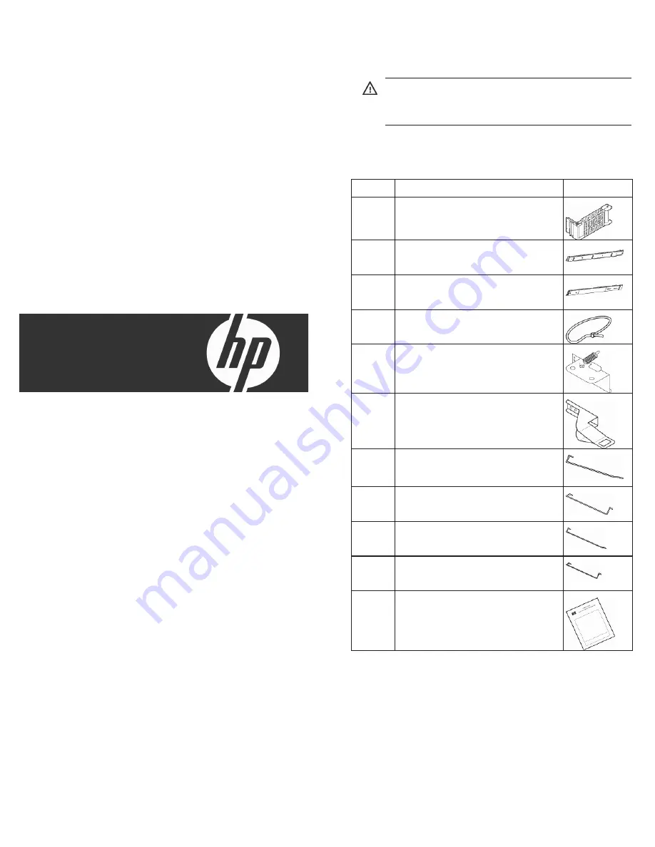


Kit contents 


WARNING:

  Do not mount this rack integration  

kit in a rack with sectional columns, such as the  
HP 5642 rack. 


If any of the following items are missing or damaged, contact 

your HP authorized reseller. The following hardware pieces 

are included in this kit. 


Quantity Description Picture 

Cable management arm 
(5069-6366) 


1 Slide, 

left 

(A6434-04045) 


1 Slide, 

right 

(A6434-04046) 


3 Cable 

tie 

(1400-3011) 


Mounting bracket and spring 
(5069-6363) 


2 Actuator 

bracket 

(5003-0540) 


1 Long 

rod, 

17U 

(5003-0538) 


1 Short 

rod, 

17U 

(5003-0541) 


1 Long 

rod, 

10U 

(5003-0539) 


1 Short 

rod, 

10U 

(5003-0542) 


1 Installation 

instructions 


© Copyright 2005, 2007 Hewlett-Packard Development Company, L.P. 

The information contained herein is subject to change without notice. The 

only warranties for HP products and services are set forth in the express 

warranty statements accompanying such products and services. Nothing 

herein should be construed as constituting an additional warranty. HP shall 

not be liable for technical or editorial errors or omissions contained herein.

Part Number 391342-004 
April 2007 (Fourth Edition) 

Summary of Contents for J1530C

Page 1: ... Mounting bracket and spring 5069 6363 2 Actuator bracket 5003 0540 1 Long rod 17U 5003 0538 1 Short rod 17U 5003 0541 1 Long rod 10U 5003 0539 1 Short rod 10U 5003 0542 1 Installation instructions Copyright 2005 2007 Hewlett Packard Development Company L P The information contained herein is subject to change without notice The only warranties for HP products and services are set forth in the exp...

Page 2: ...son Anti tip stabilizers The anti tip stabilizers provide stability and support when equipment is installed removed or accessed within the rack Stabilizer kits are available in both 600 mm 23 62 in and 800 mm 31 50 in versions Use the side feet provided with these kits to stabilize stand alone racks If you are stabilizing racks that are secured together with baying kits the side feet are optional ...

Page 3: ...h barrel nuts to the rear columns Item Reference 1 Product outline 2 Positions for mounting the cable management arm refer to step 7 3 Positions for mounting the rear of the slides refer to step 3 NOTE Single racks with a mounted component exceeding 99 79 kg 220 99 lb do not require a stabilizer kit to be installed However when extending a heavy unit for service a kit is recommended Single racks b...

Page 4: ...this procedure Failure to follow ESD safety precautions can result in damage to the server 5 Install the lift handles and place the server on the slides WARNING Use the following procedure only if a lift is not available This procedure should only be attempted by two authorized HP service personnel as a fully loaded server can weigh up to 99 79 kg 220 lb Before attempting this procedure HP recomme...

Page 5: ......

Page 6: ...ed to the floor or is used in a rack configuration with at least four bayed racks then the interlock device is not necessary If two products are installed and the rack depth is no more than 717 55 mm 28 25 in the interlock device can be installed so that you can remove one product at a time NOTE The products must be racked adjacent to each other to use the interlock device NOTE If four products ar...

Page 7: ...t 10 Install the rods as shown in the following figure Installing servers into square hole racks 1 Attach cage nuts H to the front columns Item Reference 1 Product outline 2 Positions for mounting the product refer to step 9 3 Positions for mounting the front of the slides refer to step 4 ...

Page 8: ...urements required for rack 1 465 mm 18 31 in Item Measurements required for rack 2 476 2 mm 18 75 in 3 711 to 774 7 mm 28 to 30 5 in 4 Install the right and left slides into the rack NOTE Single racks with a mounted component exceeding 99 79 kg 220 99 lb do not require a stabilizer kit to be installed However when extending a heavy unit for service a kit is recommended Single racks bolted to the f...

Page 9: ...ecautions can result in damage to the server 6 Install the lift handles and place the server on the slides WARNING Use the following procedure only if a lift is not available This procedure should only be attempted by two authorized HP service personnel as a fully loaded server can weigh up to 99 79 kg 220 lb Before attempting this procedure HP recommends that you first remove all cell boards and ...

Page 10: ...agement arm a Attach screws B to the left rear column b Slip the cable management arm over the screws B and tighten c Extend the cable management arm to the left rear side of the product d Attach the cable management arm to the studs and secure it with nuts E ...

Page 11: ...installed so that you can remove one product at a time NOTE The products must be racked adjacent to each other to use the interlock device NOTE If four products are installed in the rack and interlock devices are used then two interlock devices are needed with one device connected to the bottom two products and the other device connected to the top two products Item Reference 1 Second product Item...

Page 12: ...ed with the rp84XX and rx86XX server Item Reference 1 SEU 2 Server 1 Attach barrel nuts D to the front columns Item Reference 1 SEU outline 2 Positions for mounting the product refer to step 6 3 Positions for mounting the front of the slides refer to step 3 4 Server ...

Page 13: ...Server 3 Install the right and left slides into the rack Do not tighten the outer screws 4 Remove and discard the center screw allowing the slide to lower slightly and then tighten the outer screws 5 Place the server on the slides using a lift kit WARNING The weight of this product requires a lift to install Do not manually lift the server to install it Use a lift that can handle the load of your ...

Page 14: ...ws to secure the server to the slides NOTE Use the handles only to adjust the position of the server while it is on the slides Do not use the handles to lift the server 7 Install the cable management arm a Attach screws B to the left rear column b Slip the cable management arm over the screws B and tighten c Extend the cable management arm to the left side of the product attach it to the studs and...

Page 15: ... SEU pair installed NOTE The products must be racked adjacent to each other to use the interlock device NOTE If two pairs are installed two interlock devices are needed with one connected to the bottom pair and the other connected to the top pair Item Reference 1 SEU 2 First mounting holes for SEU 3 Server 10 Install the rods ...

Page 16: ...en proceed to step 13 12 Push the actuator bracket down while tightening the screw 13 Verify the clearance again If necessary readjust and then go to step 12 Installing SEU into square hole racks 1 Attach cage nuts H to the front columns Item Reference 1 SEU outline 2 Positions for mounting the product refer to step 9 3 Positions for mounting the front of the slides refer to step 4 4 Server ...

Page 17: ...31 in Item Measurements required for rack 2 476 2 mm 18 75 in 3 711 to 774 7 mm 28 to 30 5 in 4 Install the right and left slides into the rack Do not tighten the outer screws NOTE Single racks with a mounted component exceeding 99 79 kg 220 99 lb do not require a stabilizer kit to be installed However when extending a heavy unit for service a kit is recommended Single racks bolted to the floor or...

Page 18: ...s server must be unpacked in an ESD safe environment Observe all ESD safety precautions before attempting this procedure Failure to follow ESD safety precautions can result in damage to the server 7 Insert screws to secure the server to the slides 8 Install the cable management arm a Attach screws B to the left rear column b Slip the cable management arm over the screws B and tighten c Extend the ...

Page 19: ...EU box 2 First mounting holes for SEU 3 Server 11 Install the rods 12 Check the clearance between the short rod and the bottom actuator bracket If the clearance is less than 1 mm 0 04 in then proceed to step 13 If the clearance is greater than 1 mm 0 04 in then proceed to step 14 ...

Page 20: ...13 Push the actuator bracket down while tightening the screw 14 Verify the clearance again If necessary readjust and then go to step 13 ...

Reviews: