QUICK START GUIDE
MIO-CLASSIC-S
Mio Modero Keypad Classic Series
Overview
The Mio Modero Classic (
FG5795-01xx
, single style;
FG5795-02xx
, double style; xx
indicates color selection) provides a wide range of control capabilities in the form of
keypads that are as adept as they are elegant. Each device is available as single style
(8 button max) or double style (16 button max).
Use
KeypadBuilder
software to program these devices. The application and
documentation are available from
www.amx.com
.
Specifications
The Mio Modero device family keypad specifications are as follows:
Installation
Note: Before touching the device, discharge the static electricity from your body by
touching a grounded metal object.
The basic front and rear components of the Mio Modero are as follows:
Changing Buttons
The Mio Modero Classic is shipped with "installation" buttons; they are intended to be
place holders until your engraved buttons (designed with KeypadBuilder) arrive.
Switching Out "Installation" Buttons
1.
Pry the button using the slot on the front of the "installation" buttons to remove
them from the Mio Modero.
2.
Select the location of the custom buttons and snap them into place. Be sure to
note the orientation of the white insert on the back of the button, the notch must
be down. Insert the bottom of the button first and then push the top into place.
3.
Snap the faceplate on the mounting frame.
Changing Custom Buttons
1.
If connected, disconnect the power supply.
2.
If connected to mounting frame, place a flathead screwdriver in the notch at the
bottom right of the Mio Modero, and pry the faceplate from the mounting frame.
3.
On the back of the faceplate locate the button access points, outlined with white
circles. Using a straightened paper clip, poke through the button access points
until the buttons pop free.
4.
Snap the desired custom buttons into place. Be sure to note the orientation of the
white insert on the back of the button, the notch must be down. Insert the
bottom of the button first and then push the top into place.
5.
If the power supply was disconnected in
Step 1
, reconnect and return power to
the device.
6.
Snap the faceplate on the mounting frame.
Be certain to reprogram the Mio Modero to match the new button arrangement; use
KeypadBuilder to assign the locations. See the
KeypadBuilder Instruction Manual
available at
www.amx.com
.
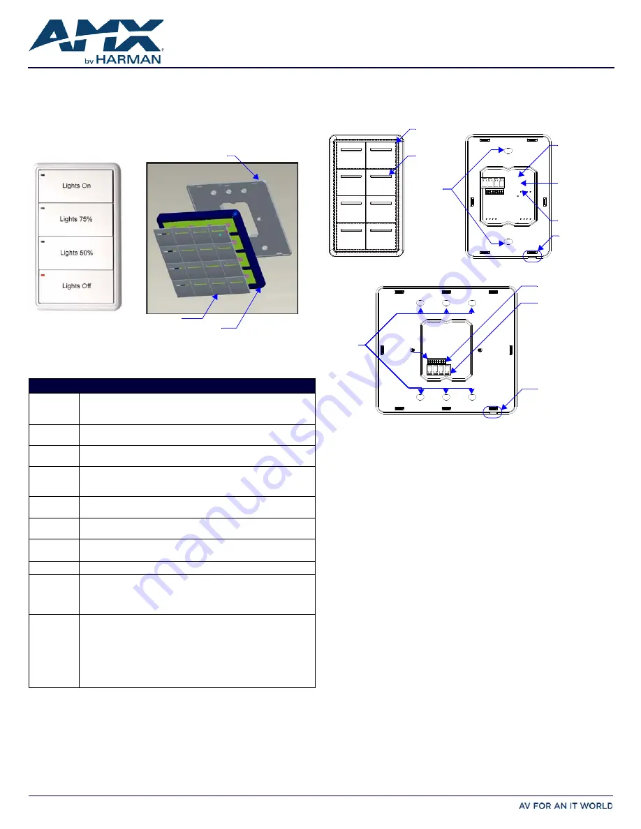
FIG. 1
MIO MODERO SINGLE STYLE CLASSIC
Specifications
Models
Available:
• MIO-CLASSIC-S (White): FG5795-01WH
• MIO-CLASSIC-S (Black): FG5795-01BL
• MIO-CLASSIC-S (
Beige
): FG5795-01BG
Power:
12 vDC, 70 - 230 mA (range depending on device type and number of
buttons)
Front Panel
Components:
• Pushbuttons - a maximum of 8 buttons on the single style and 16 buttons
on the double style, with a direct LED light.
Rear Panel
Components:
• DIP switch - 8 position mini DIP switch used to set the device address for
the keypad on the AXlink Bus.
• Wiring connection - 4 pin 3.5mm Phoenix AXlink connector.
Dimensions
(HWD):
• Single style - 4.46" x 2.71" x .57" (113.28mm x 68.83mm x 14.48mm)
• Double style - 4.46" x 4.39" x .57" (113.28mm x 111.51mm x 14.48mm)
Weight
(range):
.25 lbs (.11 kg) - .50 lbs (.23 kg) Style and number of buttons will decide
weight.
Operating
Environment:
• Operating Temperature: 0° to 50° C (32° to 122° F)
• Storage Temperature: -10° to 70° C (14° to 158° F)
Mounting:
Mounts into US and a majority of International single gang back boxes.
Included
Accessories:
• Single style mounting kit (KA-5795-01)
• Double style mounting kit (KA-5795-02)
• Installation Buttons (Classic only)
• Phoenix Connector (41-5045)
Optional
Accessories:
• Accent Frame (for some larger wallboxes):
Classic
(xx indicates color selection) - FG5795-08xx (single button);
FG5795-09xx (double button)
• Custom buttons:
Classic Colors
(xx indicates color selection) - FG5795-21xx
(4 single buttons); FG5795-22xx (2 double buttons)
• Blank buttons:
Classic Colors
(xx indicates color selection) - FG5795-07xx
Classic
Mounting Frame
Face Plate
Installation Buttons
FIG. 2
MIO MODERO FRONT AND REAR COMPONENTS
AxLink
3.5 mini Phoenix
connector
Notch to pry
faceplate free
(Rear Single)
Installation Button
Slot to pry
button free
8 position mini
DIP switch
Screw
holes
(Front Single)
Screw
holes
AxLink
3.5 mini Phoenix
connector
8 position mini
DIP switch
(Rear Double)
Notch to pry
faceplate free
PWR+
PWR+