1
R
INSTALLATION
INSTRUCTIONS
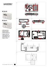
G E M - K 4 R F
Digital Icon Keypad with Integral RF Receiver
WI1179B 2/06
© NAPCO 2006
Quick Start:
1. Referring to the control panel wiring diagram, connect siren, auxiliary power, PGM
output, remote bus, earth ground, zone and telephone wiring. NOTE: See
Installation Instructions for the appropriate control panel.
2. Connect AC power first and then the battery.
3. Configure the keypad (see page 3).
4. Access the Easy Menu Driven (Dealer Program) Mode:
Press
456789 R
Press NO (
Q
)
Until “17” appears on the keypad display.
Press YES (
P
)
to Enter Easy Menu Driven Dealer Program Mode.
The Easy Menu Driven Program Mode allows you to complete all basic programming
functions by answering questions which allow the automatic programming of the
control panel.
NOTE:
The programming examples in this manual reflect the GEM-K4RF keypad con-
nected to a GEM-P1632 panel. When used with the GEM-P816 panels, the programming
is identical except for the panel limits such as: Areas = 1; Zones = 16; User Codes = 16;
Zone Doubling = Not available.
Dealer Code
This Guide includes programming instructions for the
following control panels:
•
GEM-P816 (v.9A or prior)
•
GEM-P1632 (v.9A or prior)
GEM-K4RF Keypad
This Guide is to be used in conjunction with the Programming Instruction Manual for the follow-
ing control panels:
GEM-P816 - WI995 and WI1182 (v.10 or later)
GEM-P1632 - WI897 and WI1148 (v.10 or later)
GEM-P3200 - WI818 and WI1184
GEM-P9600 - WI777 and WI1185