GE IFC66A, Instructions Manual
The GE IFC66A instructions manual is the essential companion for mastering the full potential of this product. Get the manual for free by downloading it from manualshive.com, ensuring you have all the necessary guidance you need to operate your GE IFC66A efficiently and effectively.
Share
Download


Reviews:
No comments
Related manuals for IFC66A

EJ Relays
Brand: Panasonic Pages: 4

CR Relays
Brand: Panasonic Pages: 4

IC Drivable PC Board
Brand: Panasonic Pages: 5

PZ-829 RC
Brand: F&F Pages: 7

EPP-618
Brand: F&F Pages: 12

Greengate LiteKeeper-8
Brand: Cooper Controls Pages: 8

LSR-1
Brand: Viking Pages: 2

CEY51A
Brand: GE Pages: 42
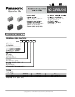
AQ-C Relays
Brand: Panasonic Pages: 5

KLF-1
Brand: ABB Pages: 20

REL 356
Brand: ABB Pages: 16

REU615
Brand: ABB Pages: 60

SRH1 Series
Brand: Autonics Pages: 5

AE 402
Brand: Adam Equipment Pages: 8

BA25
Brand: EEC Pages: 2

MFD 11 G59
Brand: Woodward Pages: 59

SHR-X L3
Brand: SVS Pages: 8

VARIMETER RCM
Brand: DOLD Pages: 8


