GE Security TruVision TVC-SD Series, Руководство по установке
Установочный мануал для серии GE Security TruVision TVC-SD доступен для скачивания бесплатно на manualshive.com. Обеспечьте безопасность своего дома с помощью этого революционного продукта. Скачайте руководство прямо сейчас и узнайте, как установить его правильно для максимальной эффективности.
Поделиться
Скачать


Отзывы:
Нет отзывов
Похожие инструкции для TruVision TVC-SD Series
Robin
Бренд: Oliver Hemming Страницы: 9

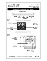
WT-5120
Бренд: La Crosse Technology Страницы: 11

VA1
Бренд: La Crosse Technology Страницы: 18
616-146A
Бренд: La Crosse Technology Страницы: 6
513-1417BS
Бренд: La Crosse Technology Страницы: 12
Soluna C79141
Бренд: La Crosse Technology Страницы: 8

Early Warning
Бренд: LoJack Страницы: 3

Okko
Бренд: Habitat Страницы: 4

D9000A SR
Бренд: DM TECH Страницы: 3

FACP
Бренд: Fire-Lite Страницы: 2

ABF-1F
Бренд: Fire-Lite Страницы: 41

RC 670
Бренд: Hama Страницы: 6

2650-660
Бренд: Firex Страницы: 8

7251
Бренд: System Sensor Страницы: 4

EM3529-NO RCC
Бренд: Clas Ohlson Страницы: 5

BEDDI
Бренд: Witti Страницы: 8

FP946
Бренд: 24/7 FIRE PROTECTION Страницы: 19

ST-CVTSD520-WSD-W
Бренд: Security Tronix Страницы: 5


