background image

- 1 -

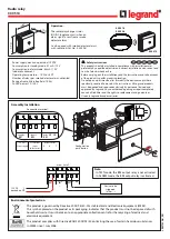
Electronic bistable pulse relay BIS-413M allows switching on or 

off the lighting or other device from several different points by 

parallel connected, momentary (bell) control switches.

The receiver is switched on after a current pulse caused by pres-

sing any momentary (bell) button connected to the relay. The 

receiver is turned off after the next impulse or automatically 

after the set off time. A longer pressing of the momentary but-

ton, lasting at least 2 seconds, turns on the relay permanently. 

The relay will be turned off only after pressing the momentary 

button again (or after a power supply failure). The supply vol-

tage is indicated by the illumination of the green LED marked 

as U. Switching the relay on and the countdown to automatic 

switch-off is signalled by the blinking of the red LED. Permanent 

switching of the relay is signalled by continuous lighting of the 

red LED.

Purpose

Functioning

F&F Filipowski sp. j.

Konstantynowska 79/81, 95-200 Pabianice, POLAND

phone/fax (+48 42) 215 23 83 / (+48 42) 227 09 71

www.fif.com.pl; e-mail: [email protected]

Do not dispose of this device in the trash along with other waste!  

According to the Law on 

Waste, electro coming from households free of charge and can give any amount to up to 

that end point of collec� on, as well as to store the occasion of the purchase of new equip-

ment (in accordance with the principle of old-for-new, regardless of brand). Electro thrown 

in the trash or abandoned in nature, pose a threat to the environment and human health.
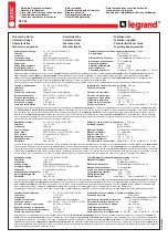
BIS-413M 

24V

Bistable relay with timing 

switch and „memory” 

contact position

Summary of Contents for BIS-413M

Page 1: ...llumination of the green LED marked as U Switching the relay on and the countdown to automatic switch off is signalled by the blinking of the red LED Permanent switching of the relay is signalled by continuous lighting of the red LED Purpose Functioning F F Filipowski sp j Konstantynowska 79 81 95 200 Pabianice POLAND phone fax 48 42 215 23 83 48 42 227 09 71 www fif com pl e mail biuro fif com pl...

Page 2: ...e relay on a rail in the control box 3 Connect the power wires to terminals 1 3 any polarity for AC voltage and for DC voltage connect to terminal 3 to terminal 1 4 Momentary switches connected in parallel connect to terminal 6 and the wire to which terminal 3 is connected 5 Powered receiver connect in series to terminals 11 12 6 Set the switch off time with the potentiometer BIS 413M 24V is not c...

Page 3: ... 3 1 3 relay power supply 9 30 V AC DC 6 control input 10 output break contact passive 11 input COM power supply contact 12 output closing contact active Wiring diagram ...

Page 4: ...0 1 0 2 s adjustment time 1 12 min power indication green LED signalling activation red LED power consumption standby 0 15 W on 0 8 W terminal 2 5mm screw terminals tightening torque 0 4 Nm working temperature 25 50 C dimensions 1 module 18 mm mounting on TH 35 rail ingress protection IP20 Technical data ...

Page 5: ...t www fif com pl The F F products are covered by a warranty of the 24 months from the date of purchase Effective only with proof of purchase Contact your dealer or directly with us F F Filipowski sp j declares that the device is in conformity with the essential requirements of The Low Voltage Directive LVD 2014 35 EU and the Electromagnetic Compatibility EMC Directive 2014 30 UE The CE Declaration...

Page 6: ......

Reviews: