ABB Relion REC615, Engineering Manual
The ABB Relion REC615, a versatile and high-performance protection relay, is specifically designed to ensure the reliable operation of electrical systems. With its extensive Communication Protocol Manual, users can easily configure and integrate the relay into their network. Download this essential manual for free from our website today!
Share
Download


Reviews:
No comments
Related manuals for Relion REC615

LTR-400
Brand: DEMA Pages: 2

MPR500
Brand: Mikro Pages: 7

PZ-829 RC
Brand: F&F Pages: 7

EPP-618
Brand: F&F Pages: 12

MPA3
Brand: Ampcontrol Pages: 41

META MEC Series
Brand: LS Pages: 4

ELMON rail 32-242
Brand: ASO Pages: 32

CIRCUIT SHIELD 49/50/51
Brand: ABB Pages: 14

RXHL 401
Brand: ABB Pages: 24

ESR4-NO-21
Brand: Moeller Pages: 6

Input+Relay R404
Brand: NetPing Pages: 36
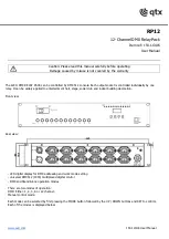
RP12
Brand: Qtx Pages: 4

NXR-100
Brand: CHINT Pages: 12

WIC1 Series
Brand: Woodward Pages: 58

TSR1-B
Brand: TopflyTech Pages: 8

TSB020ED
Brand: Tsubaki Pages: 16

MCW4
Brand: Remtrol Pages: 12

IA-3121-E
Brand: Intelligent Appliance Pages: 25


