Exar XRD9827REF, User Manual
The Exar XRD9827REF user manual is a comprehensive guide offering detailed instructions on how to efficiently operate, optimize, and troubleshoot the XRD9827REF. Easily downloadable for free from our website, users can conveniently access the manual in a PDF format to ensure maximum usability and enjoyment of this cutting-edge product.
Share
Download


Reviews:
No comments
Related manuals for XRD9827REF
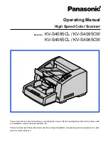
KV-S4065CL - Sf Clr Duplex 65PPM USB 2.0 Lgl 300PG...
Brand: Panasonic Pages: 87

BackHome V800
Brand: Virbac Pages: 2

WideTEK 25-600
Brand: Image Access Pages: 101

RS309
Brand: Motorola Pages: 16
Symbol STB20 Series
Brand: Motorola Pages: 24

SE4750
Brand: Motorola Pages: 86
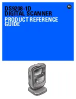
DS9208-1D
Brand: Motorola Pages: 276

Symbol MiniScan MS1207FZY
Brand: Motorola Pages: 368

D3959
Brand: Clifford James Pages: 2

SmartOffice PL4080
Brand: Plustek Pages: 39

PT2160
Brand: Plustek Pages: 59

PS3150U
Brand: Plustek Pages: 50

PS406U
Brand: Plustek Pages: 57

Sense
Brand: 3D Systems Pages: 18

Laser Scanner
Brand: Opticon Pages: 2

easy-scan
Brand: Easy Pix Pages: 32
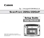
imageFORMULA ScanFront 220e
Brand: Canon Pages: 44

CAN OBD II
Brand: Centech Pages: 48


