


These instructions contain information on operating the scanner. Before reading these instructions, please read
the installation manual enclosed with this unit.
Please carefully read these instructions and the enclosed installation manual. Keep all documentation in a safe
place for future reference.
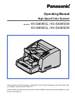
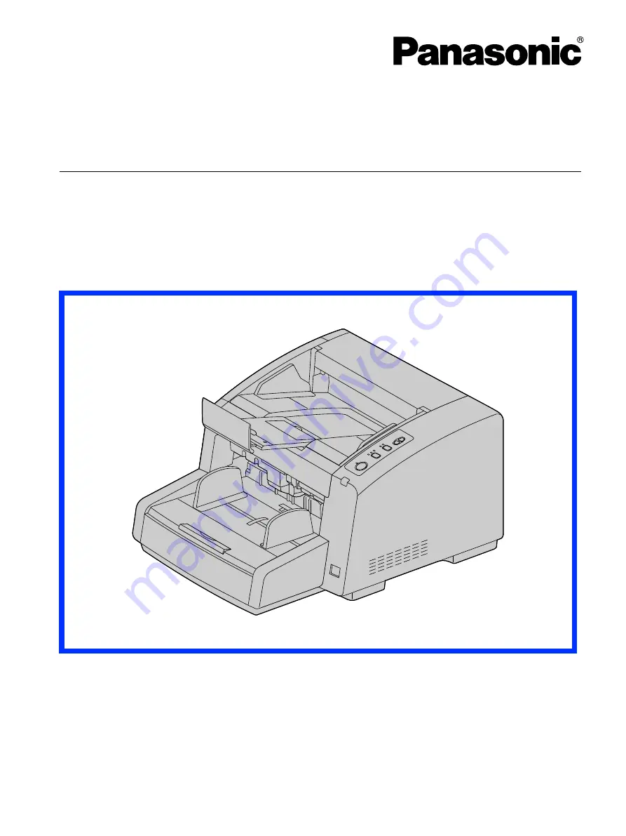
Model No.
KV-S4085CL / KV-S4085CW
KV-S4065CL / KV-S4065CW
Operating Manual
High Speed Color Scanner