background image

1

30" ELECTRIC RANGE INSTALLATION INSTRUCTIONS

1/8

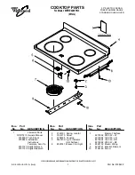
1.  Clearances and Dimensions

a. Provide adequate clearances between the range and adjacent combustible surfaces.
b.  Location—Check location where the range will be installed. Check for proper electrical supply and the stability of fl oor.
c. Dimensions that are shown must be used. Given dimensions provide minimum clearance. Contact surface must 

be solid and level.

30" minimum clearance between the top of the cooking surface 
and the bottom of an unprotected wood or metal cabinet; or 24 " 
minimum when bottom of wood or metal cabinet is protected by not 
less than ¼" fl ame retardant millboard covered with not less than 
no. 28 MSG sheet steel, 0.015" stainless steel, 0.024" aluminum 
or  0.020" copper. The minimum clearance is 0" for the rear of the 
range. Follow all dimension requirements provided above to prevent 
property damage, potential fi re hazard, and incorrect countertop 
and cabinet cuts.

Avoid locating cabinet storage space above the surface units 
to eliminate the possibility of cabinets catching on fi re, or 
personal burns from reaching for the cabinets over the heated 
units. If cabinet storage is to be provided, risk can be reduced by 
installing a range hood that projects horizontally a minimum of 
5" beyond the bottom of the cabinets.

Printed in Canada 


318201734 (1211) Rev. B

FRONT
VIEW

BACK
VIEW

FRONT

VIEW

TYPICAL CABINET INSTALLATION

SIDE
VIEW

Important Notes to the Installer

1.  Read all instructions contained in these installation instructions 

before installing the appliance.

2.  Remove all packing material before connecting the electrical 

supply to the appliance.

3.  Observe all governing codes and ordinances.
4.  Be sure to leave these instructions with the consumer.

Important Note to the Consumer

Keep these instructions with your Use and Care Guide for future reference.

All dimensions for 
electrical outlet 
location are maximum.

Cubed area shows 
where the electrical 
outlet must be 
installed for the 
range to be fl ush to 
the wall.

Wall
Edge

Terminal 

Block

Location

INSTALLATION AND SERVICE MUST BE PERFORMED BY A QUALIFIED 

INSTALLER. IMPORTANT: SAVE FOR LOCAL ELECTRICAL INSPECTOR'S 

USE. READ AND SAVE THESE INSTRUCTIONS FOR FUTURE REFERENCE.

 FOR YOUR SAFETY: Do not store or use gasoline or other 

fl ammable vapors and liquids in the vicinity of this or any other appliance.

United States

Summary of Contents for FGEF300DNB

Page 1: ... from reaching for the cabinets over the heated units If cabinet storage is to be provided risk can be reduced by installing a range hood that projects horizontally a minimum of 5 beyond the bottom of the cabinets Printed in Canada 318201734 1211 Rev B FRONT VIEW BACK VIEW FRONT VIEW TYPICAL CABINET INSTALLATION SIDE VIEW Important Notes to the Installer 1 Read all instructions contained in these ...

Page 2: ...ed Power Supply Cord or Copper Electrical Wiring Metal Conduit for hard wiring B Drill Pilot Holes and Fasten Bracket Drill a 1 8 pilot hole where screws are to be located If bracket is to be mounted to the wall drill pilot hole at an approximate 20 downward angle If bracket is to be mounted to masonry or ceramic floors drill a 3 16 pilot hole 1 3 4 deep The screws provided may be used in wood or ...

Page 3: ...ify if the anti tip bracket is engaged Lower the range by adjusting the 4 leveling legs alternatively until the range is level Check if the range is level by placing a spirit level on the oven rack Take 2 readings with the spirit level placed diagonally take a reading in one direction and then in the other direction Level the range if necessary by adjusting the leveling legs Figure 3 Range side To...

Page 4: ...ppliance must be connected to a grounded metallic permanent wiring system or a grounding connector should be connected to the grounding terminal or wire lead on the appliance Failure to do any of the above could result in a fire personal injury or electrical shock This appliance is manufactured with the frame grounded by connection of a grounding strap between the neutral power supply terminal and...

Page 5: ...e Wire Ground Bare Copper Wire To 240 V Receptacle A User Supplied Strain relief Must Be Installed at This Location Black Wire 1 1 8 2 9cm Dia Direct Connection Hole Punch Out Knockout for 1 3 8 3 5cm Dia Cord Kit Hole NOTE Be sure to remove the supplied grounding strap Figure 8 Three Conductor Wire Connection to Range If local codes permit connection of the frame grounding conductor to the neutra...

Page 6: ...ed Wires Neutral white Wire Black Wires NOTE Be sure to remove the supplied grounding strap Where local codes DO NOT permit connecting the appliance grounding conductor to the neutral white wire or if connecting to 4 wire electrical system see Figure 10 1 Be sure that no power is supplied on the cable from residence 2 Follow instructions on previous page for Four Conductor Wire Connection to Range...

Page 7: ...la existencia de suministro eléctrico adecuado y la estabilidad del piso c Se deben usar las medidas indicadas Las dimensiones indicadas proporcionan espacio mínimo La superficie de contacto debe ser sólida y estar a nivel Mínimo a la pared a cada lado de la cocina o la cocina a 36 de alto Mínimo a los gabinetes sobre cada lado de la estufa VISTA FRONTAL VISTA FRONTAL VISTA POSTERIOR Notas importa...

Page 8: ...agujeros piloto y montura de sujeción Perfore un agujero piloto de 1 8 en el lugar en el que se vayan a instalar los tornillos Si la montura se va a instalar a en la pared practique un agujero piloto con una inclinación aproximada de 20 hacia abajo Si la montura se va a instalar sobre hormigón para suelos cerámicos practique un agujero de 3 16 con una profundidad de 1 3 4 Los tornillos que se sumi...

Page 9: ...s antivuelco estén correctamente enganchados anclados Nivele la cocina Nivele la estufa si es necesario ajustando las 4 patas niveladoras con una llave ajustable Para verificar que la cocina esta nivelada coloque un nivel en las parrillas interior del horno Tome mínimo 2 lecturas con el nivel coloque el nivel en diagonal para que la cocina este nivelada de atrás hacia adelante si es necesario ajus...

Page 10: ... terminal 5 1Modelos que requieren Juego de Cordón para el Suministro de Energía Juego de cordón de 3 alambres Peligro de choque eléctrico La conexión a tierra es requerida para este electrodoméstico No conecte al suministro eléctrico hasta que el electrodoméstico este conectado a tierra de manera permanente Desconecte el suministro eléctrico hacia la caja de empalmes antes de hacer la conexión el...

Page 11: ...minal y del armazón del electrodoméstico Retenga el tornillo de la base 3 Utilizar los tuercas suministraron en el paquete de la literatura para conectar el alambre de tierra verde del cable de bronce del suministro eléctrico al armazón del electrodoméstico con el tornillo de la base usando el hoyo del armazón por donde retiró la correa de la base vea figura 7 4 Conecte el alambre neutral blanco d...

Page 12: ...ecte los dos alambres rojos juntos Donde los códigos locales NO permitan conectar el conductor de puesta a tierra del electrodoméstico al neutral blanco o si está conectado con un sistema a 4 alambres vea Figura 9 1 Desconecte el suministro eléctrico 2 Siga las instrucciones en la página anterior para la conexión del alambre de cuatro conductores a la cocina Fig 7 3 En el cortacircuito la caja de ...

Reviews: