

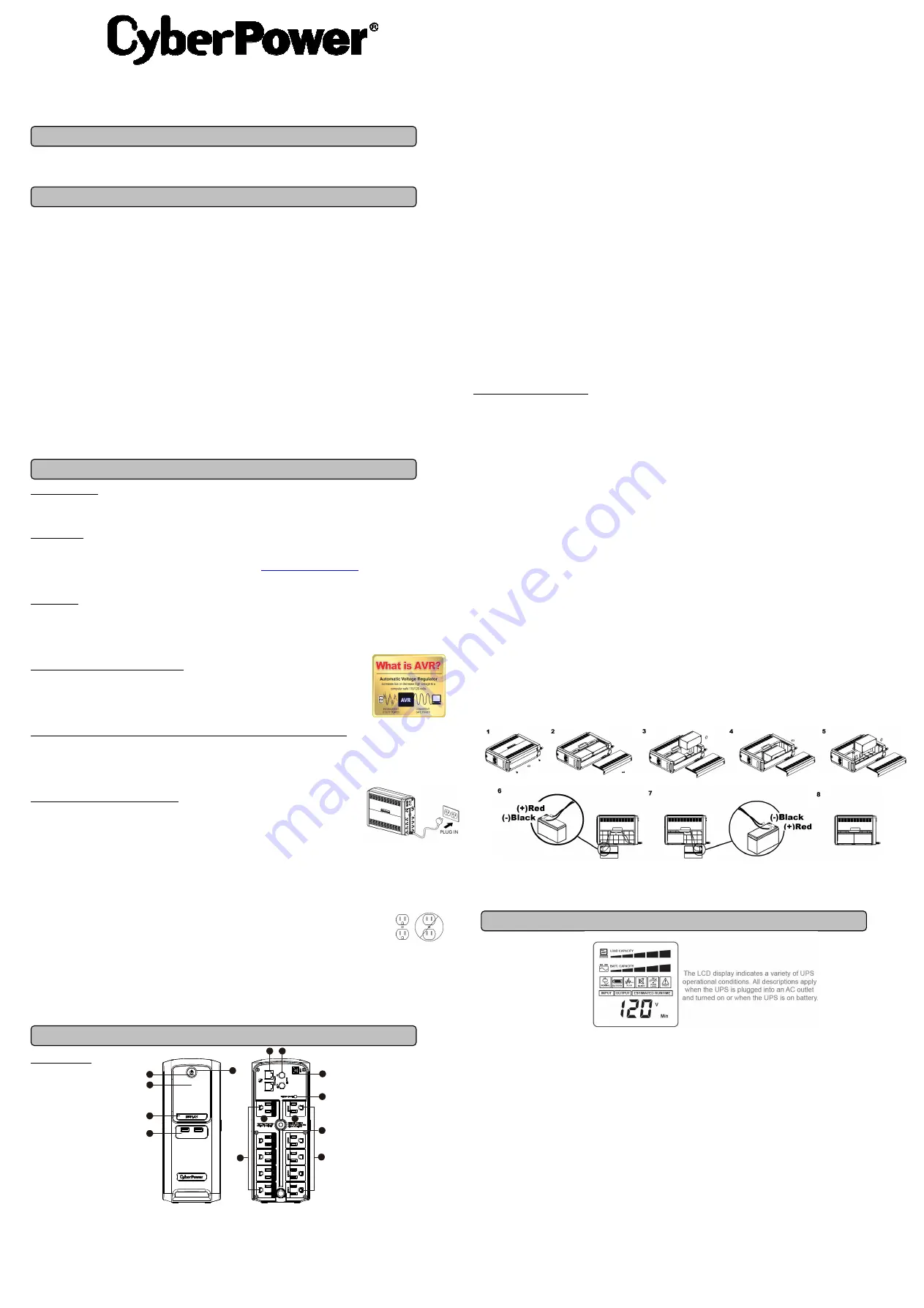
Yellow Wire to (+)Red Connector
Black Wire to (-)Black Connector
Red Wire to (+)Red Connector
Yellow Wire to (-)Black Connector
BL1250U
User’s Manual
K01-0000787-00
Thank you for purchasing a CyberPower product. Please take a few minutes to register your product at
www.CyberPowerSystems.com/Registration
. Registration certifies your product's warranty, confirms your ownership in the event of a
product loss or theft and entitles you to free technical support. Register your product now to receive the benefits of CyberPower ownership.
(SAVE THESE INSTRUCTIONS)
This manual contains important safety instructions. Please read and follow all instructions carefully during installation and operation of the unit.
Read this manual thoroughly before attempting to unpack, install, or operate your UPS.
CAUTION!
To prevent the risk of fire or electric shock, install in a temperature and humidity controlled indoor area free of conductive
contaminants. (Please see specifications for acceptable temperature and humidity range).
CAUTION!
To reduce the risk of electric shock, do not remove the cover except to service the battery. Turn off and unplug the unit before
servicing the batteries. There are no user serviceable parts inside except for the battery.
CAUTION!
Hazardous live parts inside can be energized by the battery even when the AC input power is disconnected.
CAUTION!
The
UPS must be connected to an AC power outlet with fuse or circuit breaker protection. Do not plug into an outlet that is not
grounded. If you need to de-energize this equipment, turn off and unplug the unit.
CAUTION!
To avoid electric shock, turn off the unit and unplug it from the AC power source before installing a computer component.
CAUTION!
Not for use in a computer room as defined in the Standard for the Protection of Electronic Computer/Data Processing Equipment,
ANSI/NFPA 75.
CAUTION!
To reduce the risk of fire, connect only to a circuit provided with 20 amperes maximum branch circuit over current protection in
accordance with the National Electric Code, ANSI/NFPA 70.
DO NOT USE FOR MEDICAL OR LIFE SUPPORT EQUIPMENT!
CyberPower Systems does not sell products for life support or medical
applications.
DO NOT
use in any circumstance that would affect the operation and safety of life support equipment, medical applications, or
patient care.
DO NOT USE WITH OR NEAR AQUARIUMS!
To reduce the risk of fire or electric shock, do not use with or near an aquarium.
Condensation
from the aquarium can cause the unit to short out.
DO NOT USE THE UPS ON ANY TRANSPORTATION!
To reduce the risk of fire or electric shock, do not use the unit on any transportation
such as airplanes or ships.
The effect of shock or vibration caused during transit and the damp environment can cause the unit to short out.
INTRODUCTION
Thank you for selecting a CyberPower Systems UPS product. This UPS is designed to provide unsurpassed power protection, operation and
performance during the lifetime of the product.
UNPACKING
Inspect the UPS upon receipt. The box should contain the following:
(a) UPS unit (b) User’s manual (c) USB A+B type cable (d) Function Setup Guide
*PowerPanel® Personal software is available on our website. Please visit
www.CyberPowerSystems.com
and go to the Software
Section for free download.
OVERVIEW
The
BL1250U provides complete power protection from utility power that is not always consistent. The BL1250U features 800 Joules of surge
protection. The unit provides long lasting battery backup during power outages with maintenance free batteries. The BL1250U ensures
consistent power to your computer system and includes software that will automatically save your open files and shutdown your computer system
during a utility power loss.
AUTOMATIC VOLTAGE REGULATOR
The
BL1250U
stabilizes inconsistent utility power voltage to nominal levels that are safe for equipment.
Inconsistent incoming utility power may be damaging to important data files and hardware, but with Automatic
Voltage Regulation (AVR),
damaging voltage levels are corrected to safe levels. AVR automatically increases
low utility power or decreases high utility power to a consistent and safe 110/120 volts.
HOW TO DETERMINE THE POWER REQUIREMENTS OF YOUR EQUIPMENT
1. Ensure that the equipment plugged into the outlet does not exceed the UPS’s rated capacity. If the rated capacity of the unit is exceeded, an
overload condition may occur and cause the UPS to shut down or the circuit breaker to trip.
2. There are many factors that can affect the amount of power that your computer system will require. For optimal system performance keep the
load below 80% of the unit’s rated capacity.
HARDWARE INSTALLATION GUIDE
1. Your new UPS may be used immediately upon receipt. However, after receiving a new UPS, to ensure the
battery’s maximum charge capacity, it is recommended that you charge the battery for at least 8 hours.
Your UPS is equipped with an auto-charge feature. When the UPS is plugged into an AC outlet, the
battery will automatically charge whether the UPS is turned on or off.
Note: This UPS is designed with a safety feature to keep the system from being turned on during shipment.
The first time you turn the UPS on, you will need to have it connected to AC power or it will not power up.
2. With the UPS unit turned off and unplugged, connect your computer, monitor, and any other
peripherals requiring battery backup into the
battery power supplied outlets.
DO NOT plug a laser printer, paper shredder, copier, space heater, vacuum, sump pump or other large
electrical devices into the “Battery and Surge Protected Outlets”. The power demands of these devices may overload and damage
the unit.
3. Plug the UPS into a 2 pole, 3 wire grounded receptacle (wall outlet). Make sure the wall branch outlet is protected by a
fuse or circuit breaker and does not service equipment with large electrical demands (e.g. air conditioner, copier, etc…).
The warranty prohibits the use of extension cords, outlet strips, and surge strips in conjunction with the UPS unit.
4. Press the power switch to turn the unit on. The Power On indicator lights up and the unit will “beep” twice.
If an overload is detected, an audible alarm will sound and the unit will emit one long beep. To correct this, turn the UPS off and unplug at
least one piece of equipment from the battery power supplied outlets. Make sure the circuit breaker is depressed and then turn the UPS on.
5. To maintain optimal battery charge, leave the UPS plugged into an AC outlet at all times.
6. To store the UPS for an extended period, cover it and store with the battery fully charged. While in storage, recharge the battery every three
months to ensure battery life.
7. Ensure the wall outlet and UPS are located near the equipment being attached for proper accessibility.
DESCRIPTION
1
Power Switch
Used as the master on/off switch for equipment connected to the battery power supplied outlets. (Please refer to the Function Setup Guide
for more information.)
2
Power On Indicator
This LED is illuminated when the utility power is normal and the UPS outlets are providing power, free of surges and spikes.
3
LCD module display
The LCD display shows all the UPS information using icons and messages. For more information please review the “Definitions for
Illuminated LCD Indicators” section below.
4
LCD Display Toggle/Selected Switch
The switch can be used to select the LCD display contents including Input Voltage, Output Voltage, and Estimated Run Time. Click the
button to scroll down the function menu. Pressing the button for 3 seconds will keep the LCD display always on or turn the LCD display off
while in AC/Utility power mode. For more information, please refer the Function Setup Guide.
5
USB Charging Ports
The USB Charging ports provide 5V 2.1A power output.
6
Battery and Surge Protected Outlets
The UPS has five battery powered/surge suppression outlets for connected equipment to ensure temporary uninterrupted operation of your
equipment during a power failure.
(DO NOT plug a laser printer, paper shredder, copier, space heater, vacuum, sump pump or other
large electrical devices into the “Battery and Surge Protected Outlets”. The power demands of these devices may overload and
damage the unit.)
7
Full-Time Surge Protection Outlets
The UPS has five surge suppression outlets.
8
Circuit Breaker
Located on the back of the UPS, the circuit breaker serves to provide overload and fault protection.
9
USB Ports to PC
The USB port allows connection and communication between the USB port on the computer and the UPS unit.
10 Communication Protection Ports
Communication protection ports, bi-directional, will protect a 10/100/1000 Ethernet connection (RJ45).
11 Wiring Fault Indicator (red)
This LED indicator will illuminate to warn the user that a wiring problem exists, such as bad ground, missing ground or reversed wiring. If
this is illuminated, disconnect all electrical equipment from the outlet and have an electrician verify the outlet is properly wired. The UPS will
not provide surge protection without being plugged into a grounded and properly wired wall outlet.
12 Coax/Cable/DSS Surge Protection
The Coax/Cable/DSS protection ports will protect any cable modem, CATV converter, or DSS receiver.
13 Outlets Designed for AC Adapters
The unit has two outlets spaced to allow AC power adapter blocks to be plugged into the UPS without blocking adjacent outlets.
REPLACING THE BATTERY
Replacement of batteries located in an
OPERATOR ACCESS AREA
.
1.
When replacing batteries, replace with the same number of the following battery: CyberPower / RB1270X2C for the BL1250U.
2.
CAUTION!
Risk of Energy Hazard, 24 V, maximum 9 Ampere-hour battery. Before replacing batteries, remove conductive jewelry such
as chains, wrist watches, and rings. High energy conducted through these materials could cause severe burns.
3.
CAUTION!
Do not dispose of batteries in a fire. The batteries may explode.
4.
CAUTION!
Do not open or mutilate batteries. Released material is harmful to the skin and eyes. It may be toxic.
5.
CAUTION:
A battery can present a risk of electrical shock and high short circuit current. The following precautions should be observed
when working on batteries:
1) Remove watches rings, or other metal objects.
2) Use tools with insulated handles.
CAUTION - RISK OF EXPLOSION IF BATTERY IS REPLACED BY AN INCORRECT TYPE. DISPOSE OF USED BATTERIES ACCORDING
TO LOCAL REGULATIONS.
BATTERY REPLACEMENT PROCEDURE:
1.
Turn off and unplug all connected equipment.
2.
Turn the UPS off and unplug it from the AC power source.
3.
Turn the UPS on its side.
4.
Remove two retaining screws located on the bottom of the UPS.
5.
Slide the battery compartment cover completely off of the unit.
6.
Remove the battery which is located on the right side from the compartment.
7.
Disconnect the battery wires from the right side of the battery.
8.
Slide the remaining battery from left to right and remove it from the compartment.
9.
Disconnect the battery wires from the remaining battery.
10.
Install the "left side" replacement battery by connecting the yellow wire (+) to the red connector from the battery and the black wire (-) to
the black connector from the battery. Place the battery into the left side of the compartment.
11.
Install the "right side" replacement battery by connecting the red wire (+) to the red connector from the battery and yellow wire (-) to the
black connector from the battery. Place the battery into the right side of the compartment. Note: Only new batteries should be used for
replacement and both batteries should be replaced at the same time to insure maximum life span.
12.
Slide back the battery compartment cover and tighten the retaining screws.
13.
Recharge the UPS for 8-16 hours to fully charge the battery.
REMINDER:
Batteries are considered
HAZARDOUS WASTE
and must be disposed of properly. Most retailers that sell lead-acid batteries
collect used batteries for recycling, as required by local regulations.
1.
INPUT voltage meter:
This meter measures the AC voltage that the UPS system is receiving from the utility wall outlet. The UPS is designed, through the use of
automatic voltage regulation, to continuously correct output voltage to connected equipment to a safe 110/120 voltage output range. In the
event of a complete power loss, severe brownout, or over-voltage, the UPS relies on its internal battery to supply consistent 110/120
output voltage. The INPUT voltage meter can be used as a diagnostic tool to identify poor-quality input power.
2.
OUTPUT voltage meter:
This meter measures, in real time, the AC voltage that the UPS system is providing to the computer, such as normal line mode, AVR mode,
and battery backup mode. (Note: The OUTPUT voltage meter shows the status of the battery backup outlets.)
3.
ESTIMATED RUNTIME:
This displays the run time estimate of the UPS with current battery capacity and load.
4.
NORMAL icon:
This icon appears when the UPS is working under normal conditions.
5.
BATTERY icon:
During a severe brownout or blackout, this icon appears and an alarm sounds (two short beeps followed by a pause) to indicate the UPS is
operating from its internal batteries. During a prolonged brownout or blackout, the alarm will sound continuously to indicate the UPS’s
batteries are nearly out of power. You should save files and turn off your equipment immediately or allow the software to shut the system
down.
6.
AVR (Automatic Voltage Regulation) icon:
This icon appears whenever your UPS is automatically correcting low AC line voltage without using battery power. This is a normal,
automatic operation of your UPS, and no action is required on your part.
7.
SILENT MODE icon:
This icon appears whenever the UPS is in silent mode. The buzzer does not beep during silent mode until the battery reaches low
capacity.
BASIC OPERATION
INSTALLING YOUR UPS SYSTEM
IMPORTANT SAFETY INSTRUCTIONS
DEFINITIONS FOR ILLUMINATED LCD INDICATORS
PRODUCT REGISTRATION
USB
2. 1A
USB
1
2
4
5
6
9
3
10
11
12
7
8
13
13


